Because of the holidays, TI E2E™ design support forum responses will be delayed from Dec. 25 through Jan. 2. Thank you for your patience.

This thread has been locked.

If you have a related question, please click the "Ask a related question" button in the top right corner. The newly created question will be automatically linked to this question.

LSF0108: LSF0108: Schematic Review for Bidirectional GPIOs

Part Number: LSF0108
Other Parts Discussed in Thread: TXU0104, SN74AXC4T774, SN74LV126A, SN74LXC8T245, SN74LV125A, SN74LXC8T245-Q1,

Hi,

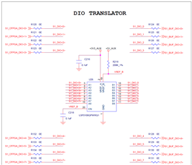
We are planning to use LSF0108QPWRQ1 for bidirectional GPIOs of our processor board, wherein each line can be configured either input or output in our software. When configured as output, Each line shall be able to drive 24mA load. Below is the screenshot of the schematic. Pls go through & advise at the earliest.
Thank you

Kind Regards

Aditya Srivatsav

  • The LSF is a passive switch. The drive strength of low signals depends on the other device driving the input; the drive strength of high signals depends on the pull-up resistor at the output (which are missing, but 24 mA is not feasible with any pull-up resistor).

    There are configurable level shifters like the SN74AXC4T774, but not for 5 V. You could build your own with multiple chips: 2x SN74LXC8T245 (or 4x TXU0104) for all signals in both directions, and 2x SN74LV125A and 2x SN74LV126A to disable the outputs of the direction that you do not need. (To get 24 mA, you need more chips and use two outputs in parallel.)

  • Hey Aditya,

    Clemens' is correct here, the LSF will support the auto-bidirectionality of the GPIO signals per channel, but won't provide the 24mA of buffering your system needs. You may see other 8 bit direction controlled translators such as the SN74LXC8T245-Q1 supporting 24mA of drive current at VCCA= 3V and up to 5V translation, but note the DIR pin configures the entire A/B bus as input or output and not individual pins. 

    Regards.

    Jack 

  • Thanks Clemens & Jack for the quick response.

    Our MCU is a COTS module & it doesn't have a control signal to program the DIR line of direction controlled buffers. We don't want to restrict the I/O usage to the user. Hence we can't opt for DIR based buffers.

    We have updated the schematic as below with pull ups as suggested. Pls advise what could be the max current that LSF0108 can drive on each line when configured as output.

    Thank you

    Kind Regards

    Aditya Srivatsav

  • Bidirectional signals cannot be buffered; when the voltages on the two sides are different, the buffer would not know which one should override the other.

    With the LSF, high signals are driven by the pull-up resistor, and low signals are driven by the MCU and passed through the switch.