This thread has been locked.

If you have a related question, please click the "Ask a related question" button in the top right corner. The newly created question will be automatically linked to this question.

SN74LVT244B: left floating

Part Number: SN74LVT244B
Other Parts Discussed in Thread: SN74ACT245

Tool/software:

When using the SN74LVT244B chip, pin 1 and pin 19 are connected to the ground. When the input pin is left floating, the output pin can output 3.3V high level signal (the VCC of the chip input is 3V3). What causes this?

When using the SN74ACT245 chip, we connect both pin 19(Output Enable) and pin 20(Power Pin) to the VCC 5V power supply, and the rest of the pins are left floating. After testing, all the data transceiver pins have 1.6V voltage difference to the ground. What causes this situation?

  • When any input is floating, you are violating the recommended operating conditions (see note 5), and correct operation is no longer guaranteed.

    When the outputs are disabled, they are in the high-impedance state. This means that they do not have any voltage; what you read is a measurement artifact caused by the limited input impedance of your measurement device.

  • Regarding the use of the SN74ACT245 chip, we measured that the data transceiver pin output a continuous and stable 1.6V level signal, which should not be caused by the error of the measurement instrument. Could you help analyze this question? What causes the continuous and stable output 1.6V level signal of these pins?

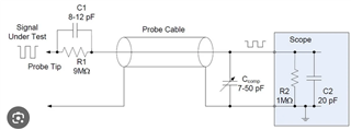
  • It's not continuous and stable output level. It's an unknown voltage level. High impedance means there is no voltage and no current flowing through the pin, it is effectively floating. Your oscilloscope probe looks like this internally:

    This internal resistance/capacitance will interfere with the high impedance measurement.

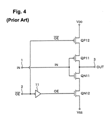
    This is what output enable circuitry looks like. When the bottom and top fet are off the impedances to VCC and GND are both infinite. The output basically becomes an open circuit.