This thread has been locked.

If you have a related question, please click the "Ask a related question" button in the top right corner. The newly created question will be automatically linked to this question.

CD4024B: CD4024 function and output behavir

Part Number: CD4024B

Tool/software:

Hi Expert,

ny customer want to use the CD4024 counter IC  for line application testing.
CH1: CD4024_Pin12_Q1
CH2: PSU Protection signal
CH3: PSU 12V output
CH4: CD4024_Pin1_Input
CD4024_Pin2_Reset is currently directly connected to ground

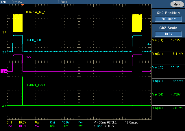
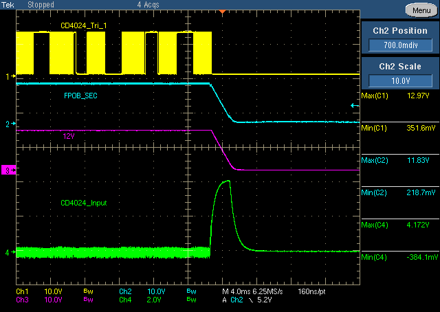
The following two pictures show the situation when the PSU protects Auto-restart.
please teach me
1. Why does Tri_1 switch by itself when I have not sent the Input signal to 4024?
2. My Reset PIN is not sending any signal, and the IC VCC is not lower than UVLO. Why does it continue to count itself?
3. How to set the output PIN if it is the same as my INPUT Pulse?

Eddie

  • Hi Eddie,

    To be honest, I am not very familiar with this device. Could you send a picture to verify that is is a CD4024B? We do have some counters that automatically count upon power up. I might have to order samples to see if that's how this device functions. Unfortunately the datasheet does not provide any logic/timing diagrams to verify if that's the case, although based off of the description alone I don't believe it should work like this.

  • The pin 1 signal is noisy. Is it possible that it is floating, and that only the oscilloscope probe pulls it down?

    Please show the schematic.