This thread has been locked.

If you have a related question, please click the "Ask a related question" button in the top right corner. The newly created question will be automatically linked to this question.

TXS0102: Use for 1kHz I2C signal with 400pF capacitance

Part Number: TXS0102
Other Parts Discussed in Thread: TXS-EVM, LSF0002, TCA9517A

Tool/software:

Hello E2E Community,

Can we use this part for 1kHz I2C signals level translation when one side of the device may have upto 400pF of capacitance (mainly CAT6 cable)?

My concern arises due to specific mentions of One Shot related ringing & <70pF capacitance, but our data speed is very low (~1kHz).

We would be able to install RC Filter if possible on the field side cable at the device input.

Our intention is to create a sacrificial IC between the cable side & the MCU pins. We will install TVS Diodes (TDS05) on the inputs - I did not see input clamp diodes to VCC on this device family - will the 7-9V clamping of this TVS affect the safety of the device - we expect surge of few microseconds in 7-9V during TVS clamping events.

Requirement is to interface an external I2C Temperature sensor to the MCU via some sacrificial device.

  • Hey Neet,

    This condition is outside of what was specified in the d/s, as we do not recommend driving a load higher then 70pF with this device. However, you can evaluate this corner case with the TXS-EVM to check for SI to see if acceptable per your system requirements. 

    Is the 400pF load limiting the data rate that you require? If so, you may also see I2C buffers that will enable higher speeds up to 1MHz so the 400pF condition is not bottlenecking your design. 

    Regards,

    Jack 

  • Hello ,

    1Khz signal is not limited by the 400pF - as I shared we are looking for a isolation device in case of EOS event occurs.

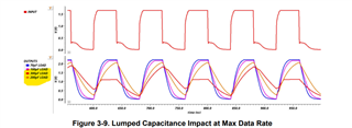
    Kindly suggest if someone from your team has experience of operating TXS- at lower speeds & higher capacitance - as the graph given in the application note with higher capacitance seems to have issues with only rise & fall time - ie waveform shape - which I believe should not be an issue at speeds as low as 1kHz - however is there anything obvious we might be missing here? That is what I am trying to understand before we invest in testing with the EVM.

    So is it a fair assumption given slow data rates (as low as 1kHz) the rise & fall time issues in the waveform as visible in the given tests might no longer be a point of concern?

    Kindly assist with best of your insights & information.

  • The TXS is designed for fast signals and a small capacitive load; this is why it has edge accelerators that time out quickly.

    The TXS is likely to work with 1 kHz signals and a high capacitive load. But the edge accelerators will not have much of an effect, and you probably want to add external pull-up resistors, so you could just as well use a simpler device like the LSF0002.

    Both the TXS and LSF are passive switches. If you want to isolate the two bus segments from each other, you need to use a buffer like the TCA9517A.