


Tool/software:
Hi all,
I am trying to figure out if all of my "Faulty" devices are from the same lot. If so, I may buy some, hopefully from a new lot, on digikey and see if my previous issues were due to a bad lot or if the part just does not work with my design. I previously used a onsemi/fairchild part which worked fine. I switched to the TI part and received unreliable performance. Lastly, I switched to a toshiba part and my reliability issues subsided. All parts seem to have identical specs. I hope it was just a bad lot.
Package Markings:
1AAKG3MG4
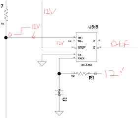
CD14538BE
Best Regards,
Kyle Hansen


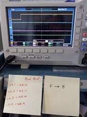
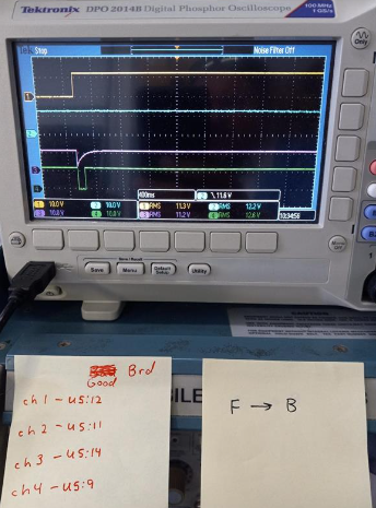


 (TR+ = blue, magenta = Q*, and Yellow = Q of the d-flip-flop)
 Blue = Q*, magenta = TR+, and Yellow = Q of the d-flip-flop)