Other Parts Discussed in Thread: TXB0104
Tool/software:
Hello,
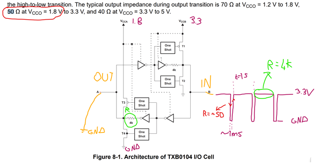
I am using TXB0104-Q1, a 4-bit bidirectional voltage-level translator with auto direction sensing and +/-15kV ESD IC with the given schematic as below:

We have the connection as given above.
The “B” is input, “A” is output
“A” was short to GND for a couple of days while I applied the shown signal to “B”.
I see that there is a 4K Ohm resistor and when it is driven high, at Output “A” with 1.8V (it is VCCA), it will limit the current from "A" when it is connected to GND. The steady-state current is about 0.45mA in my case, which is very low. Therefore I don’t have concerns about this steady-state (DC) one.
However, I could not be sure about the transition period from 3.3V to GND and GND to 3.3V applied to Input (“B”). According to the datasheet, it will have ~50 Ohm current limiting resistance and drive some current from VCCA (1.8V) to GND through 50 Ohm, which is ~36 mA for 10ns (one-shot time out).
Although the current is about 36 mA at one shot operation during the transition and the power consumption is about 700 mW for only 10ns over a 1s period pulse train (I think it should not heat up), I could not be sure since it worked in this condition more than 30 hours in total. My concern is about the reliability of the device (TXB0104-Q1).
From the datasheet:

As mentioned, it worked in this condition for a few days (maybe more than 30 hours). Would it be harmful to the device (TXB0104)? Can anyone tell me anything about its reliability?

