


FAQ: Logic and Voltage Translation > Auto-Bidirectional Level-Shifters > Current FAQ
In most cases, it is recommended to test with the device EVM instead as it yields much more accurate results under specific system loading. Simulation results captured in IBIS should not be relied entirely on signal integrity expectations due to the drive strength limitations of the LSF/TXB/TXS devices. The links below are given depending on the auto-bidirectional families EVMs.
Below are recommendations on how the models should be configured/ selected depending on translator used:
For signal integrity simulations with LSF device, models ending with “s” may be used to provide switch behavior during translation. IO models not denoted by “s” are known as termination models providing just ground clamp characteristics i.e during a HIGH-Z state.
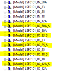
Since the LSF-type translators is comprised of passive FETs, the IO model should be selected depending on the voltage that output signal is being translated to. For example, if 1.8V to 3.3V simulation is desired, LSF0101_IO_33_S should be used to observe 3.3V output behavior. If the output side voltage is 1.8V, the LSF0101_IO_18_S model may be used to observe 1.8V output behavior.
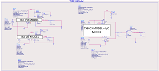
For signal integrity simulation with the TXB device, OS models and the series models should be used in conjunction to portray output behavior more accurately. The OS model describes the behavior of the one-shot impedance, while the IO model replicates the internal series resistors impedance. See below example simulation:
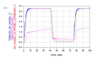
By combining both the series resistance model and the one-shot model of the device (red waveform), a more accurate representation of the output behavior can be shown compared to the output waveform of the individual OS model and IO model.