This thread has been locked.

If you have a related question, please click the "Ask a related question" button in the top right corner. The newly created question will be automatically linked to this question.

TXB0104: TXB0104 OE clarification

Part Number: TXB0104
Other Parts Discussed in Thread: TXU0304

Tool/software:

Hello,

In my system I need to scale down SPI signal and TXB0104 seems to be ticking a lot of boxes, including cost. The caveat here is that it needs to do it in almost back to front, than suggested by the default schematic, where the controlling side is at the higher potential. I understand the IC is auto bidirectional, however, this potentially causes an issue with OE.

The datasheet states OE is supplied by Vcca (display side) that needs to be lower than Vccb (CPU side). The guide (SCEA043) says that when not used, OE should be tied to Vcca. The latter suggests OE is an input and is not pulled high internally. This, in turn, means I could potentially simply scale down the incoming CPU signal to be at the correct level.

OE is advertised as referenced to Vcca, but, unless reading it incorrectly, the recommended operating conditions (see table below) suggest it can accept up to 5.5V.

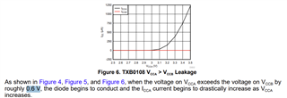
Please note that, based on the nominal voltages, the scale down would only be by 0.5V. Taking allowed max voltage into consideration, I could potentially reduce the difference to 0.3V and still leave little margin (not great, but possible). The reason I mention that is that Biasing document (SCEA060) states the difference between Vcca and Vccb must not exceed 0.6V, which, with little margin, is met anyway (again not great, but...). 

Any issues with planning to use TXB0104 'back to front'?

Can OE be used connected directly to CPU, knowing there's up to 0.5V too high?

Any issues with using scaled down OE control?

Thank you very much for help!

  • Hey Michal,

    While TXB0104 supports SPI, TXU0304 may be a more robust option due to its higher drive capability + schmitt trigger inputs. Its unique ch-configuration fits SPI closely and can achieve higher data rates than TXB0104. Power supply biasing concerns for the TXB0104 where VCCA <= VCCB is also not a concern for the TXU0304. 

    The OE pin of TXB0104 is over-voltage tolerant and capable of being biased to a higher voltage than VCCA, of up to 5.5V. Its logic threshold levels are still being referenced to VCCA however. (<35% of VCCA for valid input low, and >65% of VCCA for valid input high). 

    The reason I mention that is that Biasing document (SCEA060) states the difference between Vcca and Vccb must not exceed 0.6V, which, with little margin, is met anyway (again not great, but...). 

    This is a biasing requirement for the LSF-Type translators and not applicable for TXB-Type. Though keep in mind TXB0104 requires VCCA<= VCCB. 

    Regards,

    Jack 

  • Hi Jack,

    thank you very much for reply and suggestions.

    I did have a look at the TXU0304 and while it is more suited for native SPI and would resolve Vcca to Vccb restrictions, I cannot use it in the design. While being advertised as SPI, there's no MISO line (ie separate data return) going from  the display. Instead it has another 'MOSI style' line, Data command, needed to go from CPU to the display. The design therefore needs all 4 lines going in the same direction, while we might still need a half-duplex return over MOSI. It is an early stage and it is a suspicion only, but prefer to be ready for it. Please accept my apologies for not being precise enough in the first post.

    Speed-wise, TXB is an up to 100MHz device with design data bursts of <24MHz. Data looks really nice on an oscilloscope (great edges and minimal ringing).

    I was suspecting TXB was higher voltage tolerant, but the statement of being supplied from Vcca threw me off slightly, hence asking the question here. Thank you for confirming my suspicion. 

    As for the biasing requirements, I the 0.6V still stands for TXB. While I must have referenced a wrong paragraph, there is a clear section for TXB in SCEA060, including current consumption curve (how I missed that?) - section 1.1 (bottom), figure 6 (I attached screenshot, but only poor quality is allowed).

    Thank you very much for your help! It is very much appreciated!