This thread has been locked.

If you have a related question, please click the "Ask a related question" button in the top right corner. The newly created question will be automatically linked to this question.

LM73606: Please review the LM73606 schematic.

Part Number: LM73606

Tool/software:

Hi TI

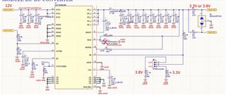
I'm designing a board using LM73606, and the concept is as follows.

Inpput V : 12V
Output V : 3.3V or 3.8V
Fsw : 500Khz
SYNC/MODE : auto mode


Question)

1. Is there no problem with the input, output cap quantity and value?

2. I'm trying to use a power inductor 4.7uH that's available for both 3.3V or 3.8V, is there any problem?
And can you recommend any specifications or part numbers?

3. What should I do with Sync mode pins NC or GND?

4. What is bias cap not mount or mount?

5. What is the result of the full circuit review? Any points to modify?

Br

chulho.Jang

  • Hi Chulho Jang,

    Please see my comments here:

    1./2. I would recommend filling in the Quickstart Calculator for this device: https://www.ti.com/tool/download/SNVR524 (this is available on the product folder). It will give you a good idea on the passive values as well. 

    3. Sync Mode Pin: The pin should not be NC - Connect to GND since you want Auto Mode
    See recommendation from Pg. 4 of the datasheet:
    "Tie to ground if not used.
    Tie to ground: auto mode, higher efficiency at light loads;
    Tie to logic high: forced PWM, constant switching frequency over load;
    Tie to external clock source: forced PWM, synchronize to the rising edge of the external clock"

    4. BIAS Cap:
    See recommendation from Pg. 3 of the datasheet:
    "TI recommends tying to VOUT when 3.3 V ≤ VOUT ≤ 18 V, or tie to an external 3.3-V or 5-V rail if available, to improve efficiency.
    BIAS pin voltage must not be greater than VIN.
    Tie to ground when not in use."

    5. Please share the filled-in quick start calculator and a higher resolution image of the schematic. 

    Also, if it is a new design - you may want to look at a newer device: www.ti.com/.../LM61460

    Thanks,

    Best Regards,

    Taru

  • Hi Taru

    Thank you for your kind reply.

    Could you please tell me your email address? The schematic is not uploaded clearly.

    Question)

    1. Should I install a 1uF cap on the bias pin I asked about above? Or should I not install it?

    2. What is the result of the full circuit review? Any points to modify?

    Br

    chulho.Jang

  • Hi Chulho,

    You can send me a private message on e2e with the schematic (See: e2e.ti.com/.../faq-how-do-i-send-and-receive-a-private-message-on-e2e-support-forums). I have sent you a connect request. 

    1. BIAS - I see you have connected it to the output - it should help with the efficiency - the bypass cap at BIAS is recommended. I would also suggest you to keep provision for a resistor between Vout and Bias if you expect/see large transients and noise at Vout. You can depopulate it if not required. 

    2. Schematic Review - as requested - please share the filled in quick start calculator with me. 

    Thanks,

    Best Regards,

    Taru