Part Number: SN74LV14A
Tool/software:
Hi team,
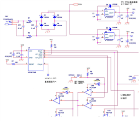
When we replaced NEXPEA's 74LV14A with SN74LV14A, we observed signal oscillation.
Please tell me if this is a defect or a specification.
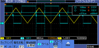
Waveform of NEXPEA's 74LV14A

Waveform of SN74LV14A
Best Regards,
Ryu.