


Tool/software:
Hi Expert,
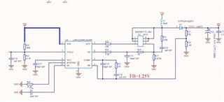
My customer using LM5022, but find one issue that, input 5.5V-6.5V, output is 40 V, under expectation. when input >6.5V, output will be over 40V, damaging next level, here is the schematic. please help to review.
Br
Chi
Tool/software:
Hi Expert,
My customer using LM5022, but find one issue that, input 5.5V-6.5V, output is 40 V, under expectation. when input >6.5V, output will be over 40V, damaging next level, here is the schematic. please help to review.
Br
Chi
