This thread has been locked.

If you have a related question, please click the "Ask a related question" button in the top right corner. The newly created question will be automatically linked to this question.

LSF0204D: Controlling LED

Part Number: LSF0204D

Tool/software:

Hello, I'm using LSF0204D to control LED.
But I have a trouble where the LED turns ON very weakly even when it should be completely OFF.
So, I'd like to know the cause of the issue.

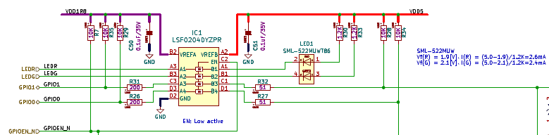
In my design, Vref_A is 1.8V and Vref_B is 5V.
A control input signal (push-pull) is connected to A port, and the output signal from B port drives the LED. LED is connected to 5V through a pull-up resistor.

When the control signal is low, LSF0204D FET is ON and the LED turns ON correctly.
But when the control signal is high, LSF0204D FET is OFF and the LED still turns ON very weakly.
With the measured voltage of the B port pin, it seems that B port accepts about 50uA current even when the FET is OFF.

I'd like to know whether 50uA is reasonable value or not.
If the "IIH" in the datasheet is the definition of the leak current, it should be less than 5uA.
Is my understanding correct?

Thank you very much in advance.

  • Hi Yoshiza-san,

    Is there a schematic that you can provide? In the event that the device is off (EN= LOW, or logic high is driven from A-side), the FET should also be off and the only current the LED should see is through the external pullup on 5V side. Can we disconnect this load and measure this current again? 

    Regards.

    Jack

  • Thank you very much for your quick comment and suggestions.
    I really appreciate your support.

    Please refer to my schematics attached.

    "LEDR" on A-side is the control signal for LED(Red).
    "LED1" is the LED (Red and Green in one package) with external 1.2K ohm pullup to 5V.

    Red and Green are almost the same design, so I'm now considering Red at first.

    I measured the current at the pullup resistor R30. It is about 19uA.
    I said 50uA in the previous question, but probably it was not exact.
    It was a value I estimated with the measured voltage at B-side being about 3.45[V].
    I suppose the difference was caused by my estimation without the actual characteristics of LED when the current is below 1mA.

    Now I actually measured the current at R30, and it was about 19uA.
    When R30 was removed, the current was 0 and of course LED did not turn ON.
    It seems that 19uA is still large enough to turn the LED ON (though very weakly).
    Is it reasonable for LSF0204D to accept 19uA when FET is OFF?

  • The LSF indeed allows a small current to flow when the voltages on both sides are not higher than Vref_A.

    See section 9.2.1.2 of the TCA9535 datasheet for a similar circuit where the forward voltage of the LED keeps the voltage too low (which leads to a different problem). A 100 kΩ pull-up, or a 47 kΩ resistor in parallel with the LED, will allow the voltage to go higher and then should shut off all current.

  • Thank you very much for your suggestion.

    For trial, I added 100K ohm pullup and confirmed that the brightness of the LED was actually reduced.
    But adding 100K ohm requires to modify the circuit(PCB), and I don't want to modify it.

    I need to reduce the brightness of the LED to be invisible when FET is off.
    If you have any good solution, I would appreciate your advice.

  • Hello Yoshizawa-san,

    Our Apps team is currently out due to the winter holidays. Please expect some delays. Thank you for your understanding.

    Regards,

    Josh

  • Hi Yoshizawa,

    The suggestion Clemens' provided would be an effective approach and would recommend moving forward with that if possible. There is also the TXB0104YZT that isn't a switch-based translator (it is a weakly buffer-based translator) that can be evaluated here. The logic of the OE is inverted here however, and during an input high state from A-side, the outputs will be weakly driven to 5V DC state via internal 4kohm series resistors. 

    Regards,

    Jack 

  • Thank you very much for your suggestion.

    I agree that Clemens' suggestion is effective, but it requires to modify the circuit.
    So, it is difficult to apply it to my product.
    In addition to controlling LEDs, I use the remaining 2 channels of LSF0204D as open drain I/Os.
    So, it is also difficult to apply TXB0104YZT because it requires to change the I/O specification.

    It is acceptable to reduce the brightness of LED to some point when it is ON.
    So, I tried increasing the external pullup value, hoping to reduce the brightness of LED when it is OFF.
    But the result was that the brightness of LED was not reduced when OFF though that was indeed reduced when ON.
    It seems that the current itself does not change so much regardless of the pullup value when FET is OFF.

    Is the value "19uA" in the expected range of "a small current" that Clemens mentioned?
    If you have any definition of the maximum current when FET is OFF, could you please provide me the specification?
    Thank you very much in advance.

  • Hi Yoshizawa-san,

    19uA was a bit higher than what I expected, (5uA similar to the IIH Enable pin spec was a closer value I had in mind). Allow me to confirm with cross function team. 

    Is this measurement consistent across all ch./ devices? 

    Regards,

    Jack 

  • Thank you very much for your comment.
    (I'm sorry for my delayed reply.)

    I measured the current (19uA) at 1 ch of 1 device.
    I did not measure the actual current of another ch of the device, but I measured the voltages on the pullup resistor and calculated that the current is almost the same.
    I did not measure the actual current of other devices, but the brightness of the LED seems to be almost the same when it should be off. So I think the current is also almost the same on other devices.

    I hope the current should be smaller than 5uA because the brightness would be reduced to 1/4.

  • Hi Yoshizawa-san,

    I see, thanks. To further decrease current, we can add reduce VREFB voltage from the 5V as that is the other method we can take without making any board modifications. Otherwise, the other method to limit the leakage current further is by adding an external pullup resistor on VREFB pin to B-side power supply. (Note this additional pullup resistor will be in series with the internal 200kohm bias resistor).

    Regards,

    Jack 

  • Thank you very much for your suggestions.
    5V is common to other devices on the board, and I cannot change the voltage.
    I'm still anxious about whether 19uA is within the expected range.
    If you have any information, could you please tell me the expected maximum current when LSF0204D is off?

  • Hi Yoshizawa-san,

    I would expect closer to 12uA (nominal) as this is what simulations show. Note the datasheet does not cover this case as this current can be controlled by the 200kohm resistor:

    There is also a 6-ch open drain buffer that can be used to drive the LEDs: https://www.ti.com/product/SN74LV6T07 

    Regards,

    Jack 

  • Thank you very much for your continuous kind support.
    Now I understood that the current would be about 12uA.
    It seems difficult to reduce the current without modifying the circuit.
    So, I'm going to try using another kind of LED with lower brightness, hoping it would be darker than the current one when off.
    After I get the result, I will report you whether it resolves my issue.

  • Hi Yoshizawa-san,

    No problem. Please reach out for any additional concerns/questions. 

    Regards,

    Jack 

  • I've got another kind of LED with lower brightness than the previous one.
    Now the LED looks darker enough when it is off.
    Thank you very much again for your continuous support you have done.