This thread has been locked.

If you have a related question, please click the "Ask a related question" button in the top right corner. The newly created question will be automatically linked to this question.

UCC28950: UCC28950PWR Behavior Under Light Load

Guru 11990 points
Part Number: UCC28950

Tool/software:

Hi,

I am experiencing issues with the UCC28950PWR under light load conditions.

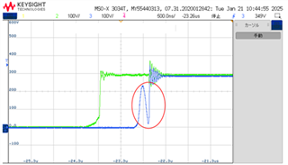
  1. The switching frequency increases significantly (e.g., ~298kHz at 1.5A load), causing large surges. What could be the root cause of this behavior?
  2. Are there recommended methods to mitigate these surges under light load?

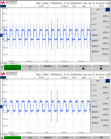
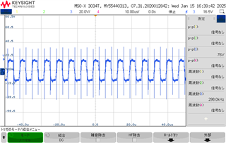
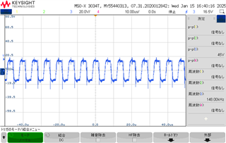
Attached are the FET gate waveforms for reference:

  • Attachment 1: 1.5A load (frequency ~298kHz)
  • Attachment 2: 3A load (frequency ~148kHz)

Your guidance on understanding and resolving this issue would be greatly appreciated.

Thanks,

Conor

  • Hello,

    I looked at these waveforms and they are set at 10 us/div.  The period is roughly 3 sub divisions for both.  They are roughly the same frequency.

    Could you double check your waveforms?

    Regards,

  • Hi Mike,

    Sorry, I will correct it. The frequency was the same.

    The surge is severe at light loads, is there any way to deal with this?

    Thanks,

    Conor

  • Hello,

    In general the freqeuncy should be fixed.  You mention the frequency cuts in half at sever light loads might indicate that you are bursting every other cycle.  This will occur when the minimum on time that is damanded by the voltage amplifier is less than minimum on time programed by Rtmin.  This actually a burst mode that is supposed to improve light load effiency.

    If this is the case and you are entering burst mode.  You might be able to resolve this with some pre-load to prevent this from happening.  The other thing that may help; as well, as adding a little more slope compensation.

    Regards,

  • Hi Mike,

    Thank you for your answer. I have one additional question.

    I can see a waveform where VDS drops once when the load is light. Do you know why this happens? I will send you the VDS waveform information, so please check it.

    VDS waveform information.xlsx

    Thanks,

    Conor

  • Hello,

    I do not see what you mentioned in the excel waveforms can you explain futher?

    Regards,

  • Hi Mike,

    Below is an excerpt from the Excel spreadsheet I sent you last time.
    VDS drops once under light load. Do you know the reason for this?

    Thanks,

    Conor

  • Hello,


    Your inquiry is under review and I will get back to you shortly.


    Regards,

  • Hi Mike,

    Thank you for checking. I look forward to your opinion.
    I also have an additional question about the RAB and RCD values.

    The datasheet indicates that RAB and RCD are often set to the same value for design simplicity. However, I would like to know if there are specific cases or design scenarios where it is recommended or advantageous to set different values for these resistors.

    In particular:

    Would differing values improve system efficiency or ZVS performance under specific conditions (e.g., varying load, MOSFET characteristics, or topology)?
    Are there any constraints or considerations when setting RAB and RCD to different values within the recommended range (13kΩ–90kΩ)?

    Thanks,

    Conor

  • Hello,

    In regards your VDS waveform it does not look like your RDELAB and RDELCD are setup correctly.  The turn on delay should 1/4 the resonate tank frequency.  The following link will bring you to an application note that shows how to setup these delay timings using a fixed delay approach.

    https://www.ti.com/lit/an/slua560d/slua560d.pdf

    Thank you for interest in Texas Instruments (TI) products.  If you have a related question, please click the "Ask a related question" button in the top right corner. The newly created question will be automatically linked to this question.

    Regards,