This thread has been locked.

If you have a related question, please click the "Ask a related question" button in the top right corner. The newly created question will be automatically linked to this question.

LSF0108: Design help and impact when using pullup resistors 1k and 198 ohm

Part Number: LSF0108


Tool/software:

Hi Experts,

Asking assistance on this query about LSF0108PWR, acting as voltage translator between FPGA (3.3Vdc) and External devices(5Vdc):

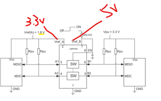
Question is if use 1k Pull Up for data lines at A(Side) of Translator Pin and 198ohm on B(side). What will be the impact?

a) In case of down Translation?
b) In case of Up translation? 

Thank you.

73,
Archie A.

  • Hi Archie,

    LSF external pullups sizing is based on the speed/ power tradeoff per your system requirements. Stronger pullups support higher DR due to quick RC time, though this also implies the additional current sunk back into driver side. 

    This set of logic minute videos cover this further:https://www.ti.com/video/series/understanding-the-lsf-family-of-bidirectional--multi-voltage-lev.html

    a.) Down translation would be 5V to 3.3V, the rise time at the outputs would be the 1kohm pullup with the cap. load on A-side. If push-pull driver/receiver, pullups on this output side may also be removed.

    b.) Up translation would be 3.3V to 5V. Pullup is needed here, and the estimated VOL due to strong pullup is equal to VOL = VIL + IOL x RON, where IOL is the current sunk through the external pullups through the B side and A side. 

    Regards,

    Jack