


Tool/software:
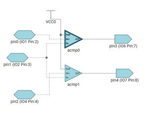
I am trying to replicate the first example, just the two analog comparator but only the first seems to work as expected.
If I use the original example it works perfectly. If I start from empty it does not work.
here is the saved file content from demo that works fine followed by the abnormal one:
/**
* These arguments were used when this file was generated. They will be automatically applied on subsequent loads
* via the GUI or CLI. Run CLI with '--help' for additional information on how to override these arguments.
* @cliArgs --device "TPLD1201_DGS_TL" --part "Default" --package "DGS (VSSOP, 10)" --product "TPLD@1.3.1+869"
* @v2CliArgs --device "TPLD1201" --package "DGS (VSSOP, 10)" --product "TPLD@1.3.1+869"
* @versions {"tool":"1.22.0+3893"}
*/
/**
* Import the modules used in this configuration.
*/
const ACMP = scripting.addModule("/ti/tpld/ACMP", {}, false);
const ACMP1 = ACMP.addInstance();
const ACMP2 = ACMP.addInstance();
const PIN = scripting.addModule("/ti/tpld/PIN", {}, false);
const PIN1 = PIN.addInstance();
const PIN2 = PIN.addInstance();
const PIN3 = PIN.addInstance();
const PIN4 = PIN.addInstance();
const PIN5 = PIN.addInstance();
const Simulation = scripting.addModule("/ti/tpld/Simulation");
const VCC = scripting.addModule("/ti/tpld/VCC", {}, false);
const VCC1 = VCC.addInstance();
/**
* Write custom configuration values to the imported modules.
*/
ACMP1.$name = "acmp0";
ACMP1.vref_sel = 26;
ACMP1.hw.$assign = "ACMP0";
ACMP2.$name = "acmp1";
ACMP2.vref_sel = 26;
ACMP2.inp_sel = 2;
PIN1.$name = "IO6";
PIN1.type = "DOUT";
PIN1.$topLabel = "LED 6\nOn if the voltage \nR1 > R2\nTop pot > middle pot\n";
PIN1.hw.$assign = "IO6";
PIN2.$name = "IO7";
PIN2.type = "DOUT";
PIN2.$topLabel = "LED 7\nOn if the voltage \nR4 > R2\nBottom pot > middle pot\n";
PIN2.hw.$assign = "IO7";
ACMP1.inp = PIN3;
PIN3.$name = "ACMP0_IN";
PIN3.sim = "sine";
PIN3.$topLabel = "R1";
PIN3.hw.$assign = "IO1";
PIN3.sine.$name = "ti_tpld_simulationOptions_SINE0";
PIN3.sine.amplitude = { val: 1.65, units: "V" };
ACMP1.inm = PIN4;
ACMP2.inm = PIN4;
PIN4.$name = "ACMPx_IN";
PIN4.sim = "sine";
PIN4.$topLabel = "R2";
PIN4.hw.$assign = "IO2";
PIN4.sine.$name = "ti_tpld_simulationOptions_SINE1";
PIN4.sine.amplitude = { val: 1.65, units: "V" };
PIN4.sine.phase = 90;
ACMP2.inp = PIN5;
PIN5.$name = "ACMP1_IN";
PIN5.sim = "sine";
PIN5.$topLabel = "R4";
PIN5.hw.$assign = "IO4";
PIN5.sine.$name = "ti_tpld_simulationOptions_SINE2";
PIN5.sine.amplitude = { val: 1.65, units: "V" };
PIN5.sine.phase = 180;
const SYSTEM = scripting.addModule("/ti/tpld/SYSTEM", {}, false);
Simulation.tstep = { val: 1, units: "us" };
VCC1.$name = "VCC0";
/**
* Connections between modules
*/
scripting.connect(ACMP1, "OUT", PIN1, "IN");
scripting.connect(ACMP2, "OUT", PIN2, "IN");
scripting.connect(VCC1, "OUT", ACMP1, "PUP");
scripting.connect(VCC1, "OUT", ACMP2, "PUP");
/**
* (x,y) coordinates for modules that are displayed in a graph
*/
ACMP1.$position = [325,155];
ACMP2.$position = [325,255];
PIN1.$position = [555,170];
PIN2.$position = [730,270];
PIN3.$position = [140,140];
PIN4.$position = [140,220];
PIN5.$position = [140,300];
VCC1.$position = [270,120];
/**
* Pinmux solution for unlocked pins/peripherals. This ensures that minor changes to the automatic solver in a future
* version of the tool will not impact the pinmux you originally saw. These lines can be completely deleted in order to
* re-solve from scratch.
*/
ACMP2.hw.$suggestSolution = "ACMP1";
SYSTEM.hw.$suggestSolution = "SYSTEM";
/**
* These arguments were used when this file was generated. They will be automatically applied on subsequent loads
* via the GUI or CLI. Run CLI with '--help' for additional information on how to override these arguments.
* @cliArgs --device "TPLD1201_DGS_TL" --part "Default" --package "DGS (VSSOP, 10)" --product "TPLD@1.3.1+869"
* @v2CliArgs --device "TPLD1201" --package "DGS (VSSOP, 10)" --product "TPLD@1.3.1+869"
* @versions {"tool":"1.22.0+3893"}
*/
/**
* Import the modules used in this configuration.
*/
const ACMP = scripting.addModule("/ti/tpld/ACMP", {}, false);
const ACMP1 = ACMP.addInstance();
const ACMP2 = ACMP.addInstance();
const PIN = scripting.addModule("/ti/tpld/PIN", {}, false);
const PIN1 = PIN.addInstance();
const PIN2 = PIN.addInstance();
const VCC = scripting.addModule("/ti/tpld/VCC", {}, false);
const VCC1 = VCC.addInstance();
/**
* Write custom configuration values to the imported modules.
*/
ACMP1.$name = "acmp0";
ACMP1.vref_sel = 26;
ACMP1.hw.$assign = "ACMP0";
ACMP2.$name = "acmp1";
ACMP2.vref_sel = 26;
ACMP2.inp_sel = 2;
PIN1.$name = "pin2";
PIN1.type = "DOUT";
PIN1.hw.$assign = "IO6";
PIN2.$name = "pin4";
PIN2.type = "DOUT";
PIN2.hw.$assign = "IO7";
const PIN3 = PIN.addInstance({}, false);
PIN3.$name = "pin1";
ACMP1.inm = PIN3;
ACMP2.inm = PIN3;
PIN3.hw.$assign = "IO2";
const PIN4 = PIN.addInstance({}, false);
PIN4.$name = "pin3";
ACMP1.inp = PIN4;
PIN4.hw.$assign = "IO1";
const PIN5 = PIN.addInstance({}, false);
PIN5.$name = "pin0";
ACMP2.inp = PIN5;
PIN5.hw.$assign = "IO4";
const SYSTEM = scripting.addModule("/ti/tpld/SYSTEM", {}, false);
VCC1.$name = "VCC0";
/**
* Connections between modules
*/
scripting.connect(ACMP1, "OUT", PIN2, "IN");
scripting.connect(ACMP2, "OUT", PIN1, "IN");
scripting.connect(VCC1, "OUT", ACMP1, "PUP");
scripting.connect(VCC1, "OUT", ACMP2, "PUP");
/**
* (x,y) coordinates for modules that are displayed in a graph
*/
ACMP1.$position = [0,0];
ACMP2.$position = [0,165];
PIN1.$position = [150,180];
PIN2.$position = [150,15];
PIN3.$position = [-195,90];
PIN4.$position = [-195,15];
PIN5.$position = [-200,180];
VCC1.$position = [-60,-65];
/**
* Pinmux solution for unlocked pins/peripherals. This ensures that minor changes to the automatic solver in a future
* version of the tool will not impact the pinmux you originally saw. These lines can be completely deleted in order to
* re-solve from scratch.
*/
ACMP2.hw.$suggestSolution = "ACMP1";
SYSTEM.hw.$suggestSolution = "SYSTEM";
Any suggestions?
Thank you in advance
Luca Pizzini
