This thread has been locked.

If you have a related question, please click the "Ask a related question" button in the top right corner. The newly created question will be automatically linked to this question.

SN74LV21A: SN74LV21ADR

Part Number: SN74LV21A
Other Parts Discussed in Thread: CD74HCT21

Tool/software:

Hello TI Team,

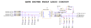
I am using the SN74LV21ADR AND gate logic IC for gate driver fault sensing. The gate driver provides a 5V high signal for a healthy state and 0V low signal for a fault condition. In my circuit, four inputs of the IC are connected with pull-up resistors. When a fault occurs, the corresponding input is pulled down to 0V.

This circuit is implemented on the power board. During power-up or when the system is running, the output of the SN74LV21ADR drops from 5V to approximately 1.8V. The recovery time varies between 6ms to 20ms or sometimes up to 40ms.

Could you please provide support in understanding this behavior and suggest ways to mitigate the voltage drop?

  • Hi Mahesh,

    Are you sure the output ever reaches 5V? It seems Vcc is 3.3V in this system and the output is gated by Vcc. 3.3V should be the highest output should ever be, realistically it should be ~2.5V. 

  • Hi,

    Yes, we have two circuits: one with 3.3V Vcc and another with 5V Vcc. I shared the 3.3V circuit in the forum. Regardless of whether we use 3.3V or 5V Vcc, the issue remains the same. What is the minimum required input voltage for the logic input signals? During start up sequence of boost converter, the input signal to the AND gate dips down to 2.5V in the 5V Vcc circuit. Please suggest a solution.

  • If you want to treat 2.5 V as a valid input voltage, then you have to use a device with lower thresholds (CD74HCT21), or use a level shifter or comparator.