This thread has been locked.

If you have a related question, please click the "Ask a related question" button in the top right corner. The newly created question will be automatically linked to this question.

SN74AVC4T245-Q1: Request for Debug Support

Part Number: SN74AVC4T245-Q1

Tool/software:

Hi Team,

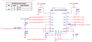
I am using the 74AVC4T245QWBQBRQ1 part on my board.

I am sending a continuous high pulse to the level translator, and when I probe the signal, I am getting <1V instead of 1.8V (VCCA = 1.8V).

When I demount the level translator, I am getting 1.8V on probing that signal.

The driver is a CMOS with a 1.8V IO level.

I have made the signal direction of all the 4-pins as A to B. Is this correct?

Below is the schematic. Can you please verify this schematic? Also requesting some debug suggestions.

  • Hello Sam,

    The schematic looks correct. When translating from A  to B, the translator inputs become high impedance. Meaning incoming signals shouldn't be impacted.

    Can we capture the voltage at DIR1 and DIR2 pins? Are you able to see any output signals?

    Regards,

    Josh