This thread has been locked.

If you have a related question, please click the "Ask a related question" button in the top right corner. The newly created question will be automatically linked to this question.

SN74LVC1G07-Q1: SN74LVC1G07-Q1

Part Number: SN74LVC1G07-Q1
Other Parts Discussed in Thread: SN74LVC1G17-Q1, SN74LVC1G125-Q1

Tool/software:

Hi Team,

I had tested the non inverting open drain buffer SN74LVC1G07QDBVRQ1 with 10K pull up resistor connected to 3.3V and 3.3V supply given to VCC.

Applied 1MHZ square wave form to input (A pin) and observed that waveform at output (Y pin) is not same as input square wave form.

As per datasheet the buffer supports up to 100MHZ frequency.

I copied tested waveform below

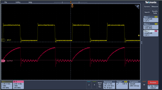
Can you please explain why this SN74LVC1G07QDBVRQ1 buffer behaving like above?

Also, confirm that these buffers can be used for SPI interface which operated at 33MHz.

Regards,

Srinivasu

  • The waveform shows that the device correctly drives the output low or deactivates the output, at the desired frequency. Your problem is that the 10 kΩ resistor is not strong enough to (dis)charge the capacitances of the traces, cables, and devices that are connected to the output. Based on the slope, I'd estimate the total capacitance to be about 30 pF.

    A 1 kΩ pull-up would speed up the rising edge, but would use a current of 3.3 mA when the output is low. For 33 MHz, you would require an unreasonably strong pull-up.

    Why are you using an open-drain buffer? A buffer with push/pull output (e.g., SN74LVC1G17-Q1 or SN74LVC1G125-Q1) would be much better suited for SPI signals.