


Tool/software:
Hello.
Here goes the schematic part related to the SN74AUP1G74.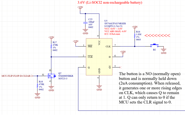
Here is the datasheet:
https://www.ti.com/lit/ds/symlink/sn74aup1g74.pdf?HQS=dis-dk-null-digikeymode-dsf-pf-null-wwe&ts=1752088729335&ref_url=https%253A%252F%252Fwww.ti.com%252Fgeneral%252Fdocs%252Fsuppproductinfo.tsp%253FdistId%253D10%2526gotoUrl%253Dhttps%253A%252F%252Fwww.ti.com%252Flit%252Fgpn%252Fsn74aup1g74
The circuit is supply by a 3.6V non-rechargeable battery of type Li-SOCl2. The flip flop keeps always supplied with its consumption of ICC = 0.9uA max, but there is the 1.8M resistor usually connected to GND through the button, so consuming 2uA (what is ok).
I considered the following. VIH = 2V min. Page 4 of the datasheet.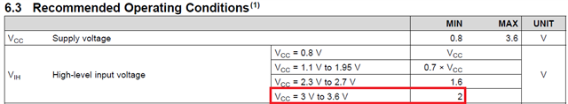
I IN = 0.5uA max, for TA = –40°C to +85°C. Page 6 of the datasheet.

VIH = 2V min.
VBAT - (0.5uA * 1.8M) = ?
3.6 - (0.5 * 1.8) = 2.7V
3.2 - (0.5 * 1.8) = 2.3V [ 3.2V would be battery in end of life ]
The results of the calculations are fine in my view, but I might be making some mistake, then I would like a review.
I wanted that 1.8Mega resistor be at least 1.8Mega, 1.8Mega would be fine if my calculations are correct.
Regards,
Jeferson Pehls.

