Other Parts Discussed in Thread: TXB0102, LSF0002, LSF0102
Tool/software:
Hi team,
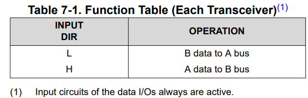
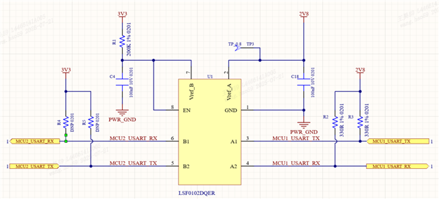
For the level shift between two MCU, the system need to config the DIR voltage level to determine direction before start shift?
Tool/software:
Hi team,
For the level shift between two MCU, the system need to config the DIR voltage level to determine direction before start shift?