This thread has been locked.

If you have a related question, please click the "Ask a related question" button in the top right corner. The newly created question will be automatically linked to this question.

TLV803E: TLV803EA26DPWR

Part Number: TLV803E

Tool/software:

Hi Team,

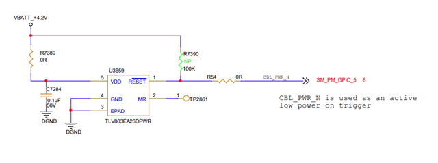
I'm using the part TLV803EA26DPWR in my design where one low pulse is required when VDD is supplied in a single power cycle.

My system needs a Low pulse as a trigger to boot up.

While supplying the VBATT_+4.2V, the system will encounter the following sequence,

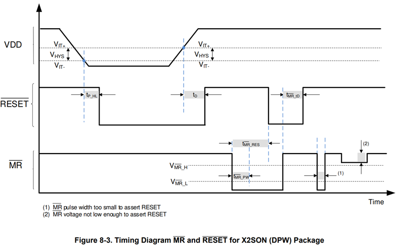
1.VDD < VPOR - undefined state of RESETn

2.VPOR < VDD < VIT-  RESETn will stable Low signal

3.VDD ≥ VIT-  RESETn will stable Low signal

4.VDD ≥ VIT+ - RESETn will stable High signal

In the datasheet, the table 8-1 fourth row whether the VDD condition (VDD ≥ VIT–) is a typo?

Also let me know the understanding on the above sequence.

  • Hi Manikandan,

    Your sequence is correct. The device has built in hysteresis which means that VDD must rise slightly above VIT- before the RESET signal will deassert. On startup when VPOR < VDD < VIT-, RESETn will be asserted (logic low on TLV803E). Once VDD ≥ VIT+, RESETn will deassert (logic high on TLV803E). VIT+ is determined by the hysteresis voltage, which can be found in the datasheet. 

    Table 8-1 does not have any typos, the last two rows describe the operation of the MRn pin. When MRn is asserted (logic low), then RESETn will assert (logic low). Figure 8-3 from the datasheet shows the function of MRn. Please note that there is an internal pull-up resistor from MRn to VDD, so it can be left floating if not in use.

    -Henry