


Part Number: SN74LVC07A
Tool/software:
Hi Sir:
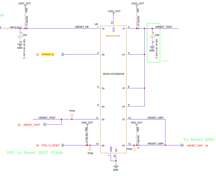
The current test circuit is shown above.
We found that when the input signals at pins 1/3/13 are all pulled high, the measured output signals at pins 2/4/12 are all low.
Why is the measured signal level low when pin 2 is pulled high to LDO1_OUT (1.8V) and pin 12 is pulled high to SW2_OUT (1.8V) through a resistor?
Please advise on this situation.
Thanks!
Best Regards
