This thread has been locked.

If you have a related question, please click the "Ask a related question" button in the top right corner. The newly created question will be automatically linked to this question.

CD4047B: CD4047 Negative-Edge Trigger Monostable Issue

Part Number: CD4047B

I have been working with the CD4047 for well over 30 years. I have just encountered a very strange anomaly. I was utilizing a series of three 4047s in a progressive timing sequence. I was using the monostable mode. The first chip was configured Positive-Edge Trigger. The following two stages were configured Negative-Edge Trigger. The circuit was functioning as expected. I then modified the timing components and added a new front end timing pulse. The new front end was added to the design to facilitate external triggering of the timers. I added a jumper to be able to switch between the onboard oscillator used for calibration. The nature of the anomaly:

Since the above-mentioned modifications, the first one-shot is functioning normally, the next one-shot is outputting a steady high.

 I consulted Grok seeking troubleshooting advice. It noted that the monostable Negative-Edge Trigger had a tendency to be temperamental. I implemented the suggestions but have been unable to get the oneshot to function.

The circuit is built on a Radio Shack 276-168B Breadboard PCB.

I have tried replacing the 4047 with different build dates chips with the same result.

I have verified that the wiring is correct numerous times.

I removed the third chip to see if that was causing the issue. No change.

I added a CD40106 between the first and second oneshot. No change.4047 Oneshot Schematic.jpg
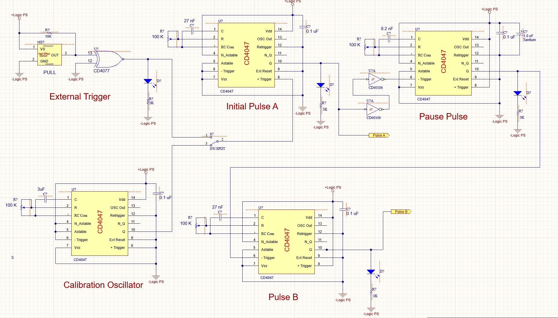
This is the as-built schematic.

  • Hi Gerard,

    Please provide a scopeshot showing the input and output waveforms of the oscillator that is behaving abnormally.

  • Hi Ian.

    I've been distracted the past couple of days. 

    I've now circled back to this project.

    I've since tried adding CD40106s between each of the oneshots. No Change.

    Here are the scope shots you requested.

    This first one is the output of the first stage at pin 10.

    The blue trace is the input to the second stage on pin 6.

    This next image is depicting the output of stage one and the output of the second stage at pin 10.

    The second stage output is latched high.

    There is also no output at pin 13. It is also latched high.

    Here is the updated schematic.

    Thank you for any insight you can provide. This is very baffling.

    Make yourself a Great Day!

  • Hi, could you provide a scope shot showing the RC node during operation? What is the value that the Pot is set to?

  • Hi Ian,

    Thanks for getting back to me.

    This first image is depicts the output of the first oneshot, yellow trace.

    The blue trace is the image from pin one.

    This second scope-shot is of the first oneshot output, yellow.

    The blue trace is the what is seen on both pins 2 & 3, zero volts.

    Pins 1, 13 & 10 are all at the same level as the first image.

    The value the pot is set to is 37k.

    I'm looking forward to what you can divine.

    Make yourself a Great Day!

  • Hi,

    Would it be possible to short pin 3 high using a jumper wire while pin 3 and pin 2 are shown on the scope? This should force a state change in the internal gates.

  • Hi Ian,

    Here are the images from the the test that you proposed.

    This first image is of the second oneshot being driven as depicted in the previous posts.

    The yellow trace is pin 3 un-shorted.

    The blue trace is pin 2.


    This image is showing pin 3 being jumpered high, and pin 2 remaining low.

    Thank you hanging in, this is a head scratcher.

    Make it a Good Day!

  • Gerard,

    Is there any way you can make the -Trigger pin idle high by default for your negative-edge triggered devices? So, use only one inverter, or the negative/nQ output of the first stage device to drive the negative-edge triggered stages.

    I'm curious if the negative-edge input was intended to work with an input that's high by default and then transitions low.

    Best,

    Malcolm

  • Hi Malcom,

    Interesting question.

    I'm in the middle of another project at the moment. As soon as I can break away I will configure the hardware to test holding the input high,

    Should be able to post result in a couple of hours.

    Make it a Good One! 

  • Hi Malcom,

    No Joy.

    Also tried it with a new chip. Same result. Output latched high.

    Make it a good One!

  • Gerard,

    Sad about that. The only thing I can think of is to test the negative-edge/not working monostables in the positive-edge triggered configuration (same as the first monostable that we know to be working) to see if the issue is related to the negative edge trigger specifically.

    I've ordered some samples to see if I can recreate the problem but these will probably take about a week to arrive, and I might not be able to test them before thanksgiving.

    Best,

    Malcolm

  • Hi Malcom,

    Reconfigured the oneshot to positive edge trigger. It functioned normally.

    Tomorrow I will configure it as a negative edge trigger and report the result.

    If it still fails, I will build the circuit on a new breadboard. 

    Make it a good evening.

  • Good morning Malcom,

    Well all of the mucking about with the circuit seems to have resolved the issue,

    The circuit is now functioning. There probably was some solder issue that was hiding.

    To answer your question about the inverted input on the Negative-Edge Trigger; the effect that it has is to advance the pulse ahead of the input pulse.

    After I reverted the input to the non-inverted, the pulse followed the input pulse.

    Your suggestion to test the Positive-Edge Trigger uncovered the solder issue.

    Make it a Great Day!

  • Hi Gerard,

    Glad to hear it!

    Best,

    Malcolm