This thread has been locked.

If you have a related question, please click the "Ask a related question" button in the top right corner. The newly created question will be automatically linked to this question.

MSPM0G5187: Request for Detailed Guidance on MSPM0G5117 DFU Flashing via TinyUSB

Part Number: MSPM0G5187
Other Parts Discussed in Thread: MSPM0G5117, , UNIFLASH

Hi, 

We need to flash the firmware via TinyUSB on the MSPM0G5117 MCU, which belongs to the same family as the MSPM0G5187.

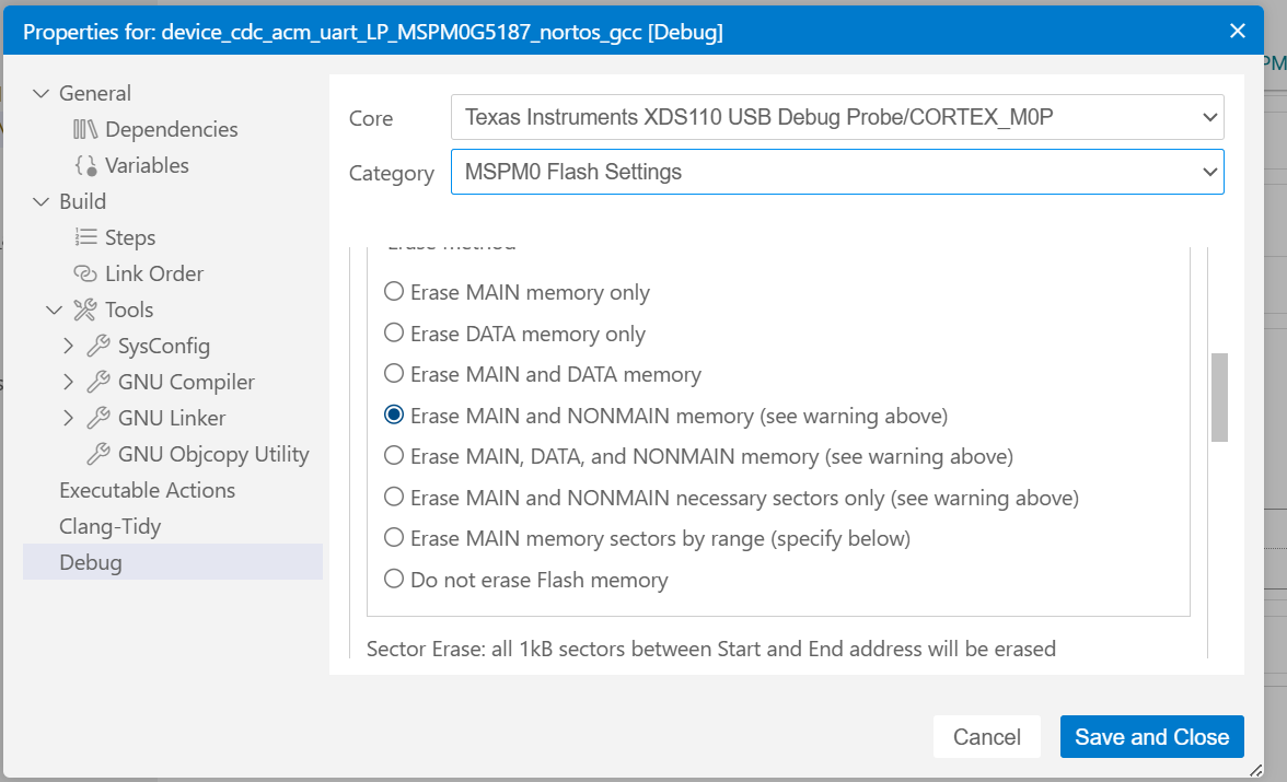
As suggested by the local TI team, we added the Config NVM settings and modified the BSL Invoke Pin configuration accordingly (reference image attached). Additionally, under:

Project → Properties → Debug

the checkboxes for both Main and Non-Main memory erase were enabled before flashing the code.

After flashing, we are following the below BSL entry sequence:

  1. Hold the BSL button
  2. Hold the Reset button
  3. Release Reset after 1 second
  4. Release BSL after 2 seconds

However, the COM port is not becoming visible, and the system is not entering DFU mode as expected.

As per the README available under:

SDK → TinyUSB → BSL → Readme.html

I have already completed the mentioned setup steps, including installation of Zadig and dfu-util.

In our case, Config NVM modification is mandatory because, by default, BSL mode is triggered using a HIGH signal. However, based on our hardware design, the trigger must work in LOW condition, which is why the Config NVM changes are required.

At this stage, both the .out and .bin files have been successfully generated, and we would like to proceed with direct DFU flashing to the MSPM0 device.

Currently, we are facing two major issues:

  1. Entering into BSL / DFU Mode
    • The device is not reliably entering DFU mode after the configured button sequence.
    • COM port is not getting detected after the BSL invoke sequence.
  2. Flashing the Firmware Without XDS110 Debugger
    • Our requirement is to flash the firmware directly through TinyUSB/DFU without using the XDS110 debug interface.
    • We need confirmation on the correct process and supported method for standalone USB flashing.

Additionally, we request guidance on the following points:

  • Correct DFU commands required for flashing
  • Exact execution order / flashing sequence
  • Recommended tool or simplified method for direct TinyUSB flashing
  • Validation whether the current Config NVM settings are correct for DFU operation

Since the device is expected to already be in DFU mode, it would be very helpful if you could share a detailed step-by-step flashing procedure, along with any reference scripts or tools available for this process.

Looking forward to your guidance and support in resolving this issue.
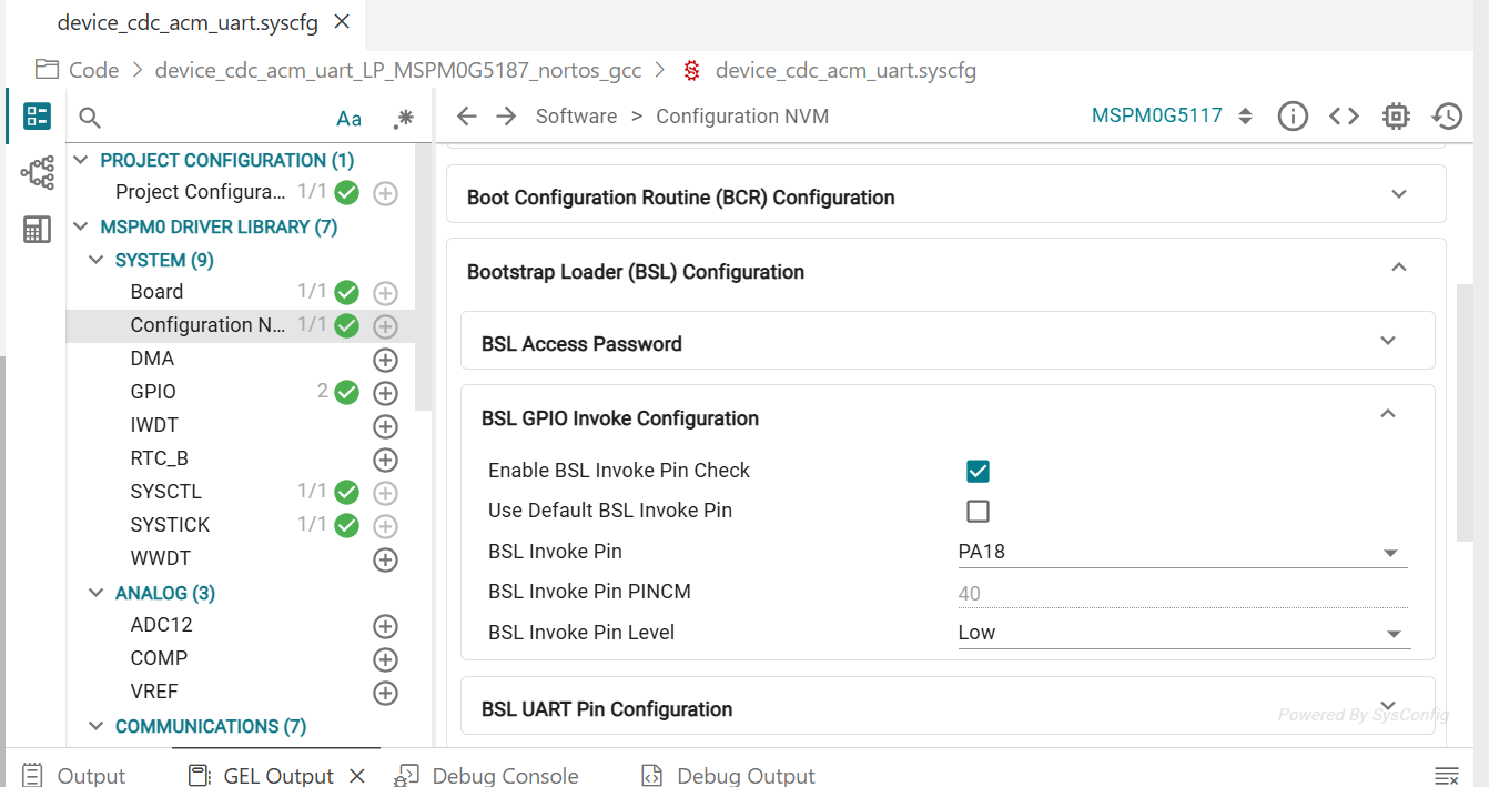

image.png

image.png

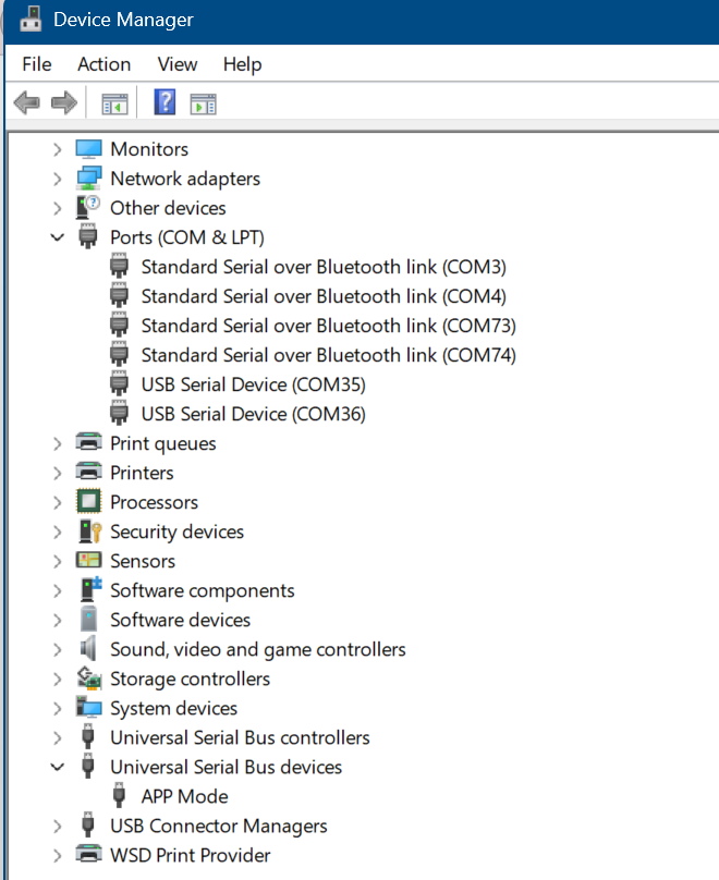
Before Inoke sequence 
image.png

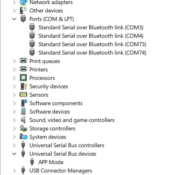
After BSL Invoke Sequence 
image.png


  • Hi Ramanathan,

    As suggested by the local TI team, we added the Config NVM settings and modified the BSL Invoke Pin configuration accordingly (reference image attached). Additionally, under:

    There is no need to config NVM for BSL mode. We enable the BSL/DFU mode by default. Please execute factory reset to recover the device to blank.

    Entering into BSL / DFU Mode
    • The device is not reliably entering DFU mode after the configured button sequence.
    • COM port is not getting detected after the BSL invoke sequence.

    The flow is correct, while the NVM is not required to configured.

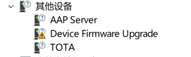
    After the button sequence, users should find the Device Firmware Upgrade (DFU) show in the "Other Device"

    Flashing the Firmware Without XDS110 Debugger
    • Our requirement is to flash the firmware directly through TinyUSB/DFU without using the XDS110 debug interface.
    • We need confirmation on the correct process and supported method for standalone USB flashing.

    Please check the documents below, it gives the detailed instructions for users to start flashing with DFU:

    ti\mspm0_sdk_2_10_00_04\tools\bsl\dfu_host_utility

    • Correct DFU commands required for flashing
    • Exact execution order / flashing sequence
    • Recommended tool or simplified method for direct TinyUSB flashing

    These are all well clarified in the readme file of the DFU.

    Validation whether the current Config NVM settings are correct for DFU operation

    MSPM0G5117 enable DFU by default, normally we doesn't require any NVM settings.

    Unless the hardware schematic uses other BSL/DFU invoke pin or polarity (default is PA18, with HIGH polarity invocation).

    B.R.

    Sal 

  • Hi Sal Ye, 

    As per the instructions provided in the SDK Readme file, we generated the .txt file using the TI Clang compiler. However, the code is not flashing onto the device.

    The device successfully enters BSL mode, but the flashing process fails.

    For your reference, we have attached the log file.
    Kindly review it and help us resolve the issue.

    dfu-util 0.9
    
    Copyright 2005-2009 Weston Schmidt, Harald Welte and OpenMoko Inc.
    Copyright 2010-2016 Tormod Volden and Stefan Schmidt
    This program is Free Software and has ABSOLUTELY NO WARRANTY
    Please report bugs to http://sourceforge.net/p/dfu-util/tickets/
    
    Opening DFU capable USB device...
    ID 2047:0210
    Run-time device DFU version 0110
    Claiming USB DFU Interface...
    Setting Alternate Setting #0 ...
    Determining device status: state = dfuIDLE, status = 0
    dfuIDLE, continuing
    DFU mode device DFU version 0110
    Device returned transfer size 512
    Copying data from PC to DFU device
    
    Download	[                         ]   0%            0 bytes failed!
    state(10) = dfuERROR, status(2) = File is for this device but fails some vendor-specific test
    

  • Hi Ramanathan,

    I tried the hostutility_interface.exe and all works fine:

    Welcome to Interface Utility!
    Performing initial setup...
    Checking device connection...
    data written to output file: image.dfu
    the output data written in image.dfu
    
    Getting device info...
    data written to output file: image.dfu
    the output data written in image.dfu
    
    output file output/device_info.txt
    the send staus is 1
    Bin file path : output/readback.bin
    Output file path : output/device_info.txt
    Hex data of given .bin file has been written to output/device_info.txt
    Initial setup complete.
    
    Enter the choice based on the command mapping shown below:
    1: Program Device
    2: Readback Memory
    3: Standalone Verification
    4: Mass Erase
    5: Get Device Info
    6: Factory Reset
    7: Flash Range Erase
    8: Start Application
    9: Unlock BSL
    10: Toggle logs (currently OFF)
    11: Toggle send file (currently ON)
    12: Calculate file checksum
    0: Exit
    Choice: 9
    Password file (.txt) [password.txt]: inputs/sample_password.txt
    writing to file firmware_0_21.dfu with address 0
    File written successfully: firmware_0_21.dfu
    sending file: firmware_0_21.dfu
    
    Do you want to continue? (y/n): y
    
    Enter the choice based on the command mapping shown below:
    1: Program Device
    2: Readback Memory
    3: Standalone Verification
    4: Mass Erase
    5: Get Device Info
    6: Factory Reset
    7: Flash Range Erase
    8: Start Application
    9: Unlock BSL
    10: Toggle logs (currently OFF)
    11: Toggle send file (currently ON)
    12: Calculate file checksum
    0: Exit
    Choice: 1
    Input file (.txt or .bin) [firmware.txt]: inputs/test_firmware.txt
    Enable checksum validation? (y/n): y
    Enter expected checksum (hex format, e.g., 0x1234ABCD or 1234ABCD, or press Enter to skip):
    writing to file firmware_0_20.dfu with address 0
    File written successfully: firmware_0_20.dfu
    sending file: firmware_0_20.dfu
    DFU download may have failed. See debug/dfu_log.txt for details.
    writing to file firmware_0_20.dfu with address 0
    File written successfully: firmware_0_20.dfu
    sending file: firmware_0_20.dfu
    
    Do you want to continue? (y/n):
    

    I suggest you first try this method to see if there any issues in your set up.

    Note that users need unlock BSL with password before do any read/program behavior.

    B.R.

    Sal

  • Hi Sal Ye,

    Thanks for your reply.

    After testing the procedure, I am facing the following issues:

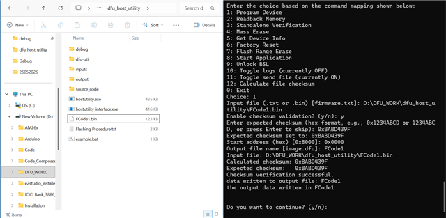
    1. During the flashing process, the operation stops in the middle. For your reference, I have attached a picture.

    As per the instructions you shared, I followed the below DFU sequence:

    • Entered DFU Mode

    • Unlocked BSL

    • Entered Sample Password

    • Password Accepted

    • Started Code Flash using the .bin file (128 KB)

    However, after sending the .bin file, the flashing process gets stuck. Please share the correct flashing procedure and guide me on how to resolve this issue.

    1. During another flashing attempt, the process again stopped in the middle. After that, when I tried to enter DFU Mode again, I started getting the error: MSPM0 core failed.

    Let me know how to recover from this issue. I also tried using CCS, but the same issue still persists.

           3.Share the .bin file flashing procedure similar to the .txt flashing procedure you shared earlier.

    Also guide me on how to generate .txt or .bin files from CCS builds. Currently, CCS generates only the .out file, and I am using PowerShell commands to manually convert it. Please share the recommended conversion process and required tools/commands.

    MSPM0 Core Failed:

    Debug_upload_log FYI:

    dfu-util 0.9
    
    Copyright 2005-2009 Weston Schmidt, Harald Welte and OpenMoko Inc.
    Copyright 2010-2016 Tormod Volden and Stefan Schmidt
    This program is Free Software and has ABSOLUTELY NO WARRANTY
    Please report bugs to http://sourceforge.net/p/dfu-util/tickets/
    
    Opening DFU capable USB device...
    ID 2047:0210
    Run-time device DFU version 0110
    Claiming USB DFU Interface...
    Setting Alternate Setting #0 ...
    Determining device status: state = dfuIDLE, status = 0
    dfuIDLE, continuing
    DFU mode device DFU version 0110
    Device returned transfer size 512
    File exists: Cannot open file ../output/readback.bin for writing
    

    output/*.bin:

    Regards 
    Ram

  • Hi Ram,

    I am OOO till next Tuesday. I'll check when I back office.

    My initial though is that your firmware has some issues - is this firmware works fine when you using SWD interface to flash?

    B.R.

    Sal

  • Hi, 
    Yes, the firmware is working correctly when flashed using the XDS110 debugger. Up to this stage, the local TI team has guided and validated the complete process.

    Regards, 
    Ram

  • Hi Sal,

    Can you suggest any methods to popery generate .bin file that can be flashed?

    The observation is that hex files are working correctly when flashed through Uniflash - but non main reign gets corrupted once flashed after converting it to bin.

    we are using objcopy library to convert the files. below is the command that is being used  - 

    "D:\Code_Composser\9 2019-q4-major\arm-none-eabi\bin\objcopy.exe" -O binary --gap-fill 0xFF --pad-to 0x00020000 -j .text -j .rodata -j .data -j .cinit -j .const -j .init_array -j .interrupts "FCode.out" "firmware2505.bin"

    Regards,

    Megh 

  • Hi Megh, Ramanathan,

    Please see my comments below:

    1. How to generate hex/txt file in CCS

    See below guidance: https://www.ti.com/lit/ug/slaaed1g/slaaed1g.pdf 

    2. How to recover the device from M0 core connected failed

    See below guidance: https://www.ti.com/jp/lit/ug/slaaeo4/slaaeo4.pdf 

    3. How to use DFU to program:

    I follow the same approach to write the full 128KB firmware without any issues:

    Test Firmware: test_firmware.txt (maybe you can double try this file)

    Could you double confirm the version you are using for DFU deployment?

    I am using: 

    B.R.

    Sal

  • Megh,

    For nonmain firmware, I think there has some issues.

    I see it also failed in my side including txt format. The bin format does not support nonmain programming after check with internal team.

    I'll test the txt format flow including main+nonmian program and feedback later when i have some progress.

    B.R.

    Sal

  • Hi Megh, Ramanathan,

    Please see my update on the main+nonmain program flow via DFU interface:

    1. Enter the DFU mode by PA18 pull-high and reset (or other DFU invoke flow)

    2. Unlock DFU with password file

    3. Execute factory reset to erase main+nomain flash regions [NOTE: after factory reset, MCU must keep in DFU mode until writing new nonmain firmware. If reset or power off happens, MCU will enter locked state due to the empty nonmain configuration and cannot recover]

    4. Program with nonmain.txt file only [NOTE: always execute factory reset (or execute flash range erase for nonmain region) before write nonmain.txt file, otherwise, the MCU might enter locked state after program!]

    5. After program success, program with main.txt file (as it execute factory reset command, main flash region is ready to program without another erase command]

    6. Finish the program

    Now the DFU host tool has some issues when program main+nonmain within same txt file, I find it suddenly exist when program main+nonmain. I have reported the issues to internal team to further anaysis.

    When this happens, follow the below guidance to recover (NOTE: must keep the MCU not reset before recover, otherwise, the MCU will be permanently locked)

    1. Reopen the hostutility_interface.exe again.

    2. Unlock DFU with password

    3. Execute factory reset

    4. Program nonmain.txt file to restore the nonmain configuration

    5. Now the MCU can be reset or power off.

    B.R.

    Sal

  • Hi Sal,

    Thanks for the reply here.

    Can we have quick call with customer to help him out here. Below is the latest status.

    1. Successfully able to generate .bin file without non main changes 
    2. Successfully able to flash it through UNIFLASH.
    3. Application is workign as expected with uniflash.
    4. When trying to use DFU tool to flash devcie belwo error is occuring. 

    As per your instructions, the .bin file was successfully created with a file size of 123 KB.

    After that, I followed the same flashing procedure; however, the code was not flashed successfully. During the process, after checksum verification, the operation exited without failure report.
    In the logs download is still 0 percent. 

    Regards,
    Megh 

  • Hi Megh,

    I suppose the TXT file should work.

    I also test the bin file in my side, it works with below interface log, please refer to the flow I generates, I see the command of the file name, path is not the same as mine, below is the reference:

    Welcome to Interface Utility!
    Performing initial setup...
    Checking device connection...
    data written to output file: image.dfu
    the output data written in image.dfu
    
    DFU download may have failed. See debug/dfu_log.txt for details.
    Getting device info...
    data written to output file: image.dfu
    the output data written in image.dfu
    
    output file output/device_info.txt
    the send staus is 1
    Bin file path : output/readback.bin
    Output file path : output/device_info.txt
    Hex data of given .bin file has been written to output/device_info.txt
    Initial setup complete.
    
    Enter the choice based on the command mapping shown below:
    1: Program Device
    2: Readback Memory
    3: Standalone Verification
    4: Mass Erase
    5: Get Device Info
    6: Factory Reset
    7: Flash Range Erase
    8: Start Application
    9: Unlock BSL
    10: Toggle logs (currently OFF)
    11: Toggle send file (currently ON)
    12: Calculate file checksum
    0: Exit
    Choice: 9
    Password file (.txt) [password.txt]: inputs/sample_password.txt
    writing to file firmware_0_21.dfu with address 0
    File written successfully: firmware_0_21.dfu
    sending file: firmware_0_21.dfu
    
    Do you want to continue? (y/n): y
    
    Enter the choice based on the command mapping shown below:
    1: Program Device
    2: Readback Memory
    3: Standalone Verification
    4: Mass Erase
    5: Get Device Info
    6: Factory Reset
    7: Flash Range Erase
    8: Start Application
    9: Unlock BSL
    10: Toggle logs (currently OFF)
    11: Toggle send file (currently ON)
    12: Calculate file checksum
    0: Exit
    Choice: 4
    data written to output file: image.dfu
    the output data written in image.dfu
    
    
    Do you want to continue? (y/n): y
    
    Enter the choice based on the command mapping shown below:
    1: Program Device
    2: Readback Memory
    3: Standalone Verification
    4: Mass Erase
    5: Get Device Info
    6: Factory Reset
    7: Flash Range Erase
    8: Start Application
    9: Unlock BSL
    10: Toggle logs (currently OFF)
    11: Toggle send file (currently ON)
    12: Calculate file checksum
    0: Exit
    Choice: 1
    Input file (.txt or .bin) [firmware.txt]: inputs/test_firmware_main.bin
    Enable checksum validation? (y/n): n
    Start address (hex) [0x8000]: 0x0
    Output file name [image.dfu]: test_bin.dfu
    data written to output file: test_bin.dfu
    the output data written in test_bin.dfu
    
    
    Do you want to continue? (y/n):

    Then I read back the memory by UNIFLASH and verified it has been programmed successfully:

    Some tips:

    1. mass erase before load new firmware

    2. make sure the file name and path is correct

    B.R.

    Sal

  • Hi Sal,

    Thanks for the support here.

    This resolved the issue and Ramanathan is testing few more configuration now. We will reach out to you I any thin is required.

    Regards ,

    Megh