Part Number: TXB0102

In this schematic diagram, when the VCCB outputs a high level, T1 conducts. What is the current loop of the internal 4K resistor, and why is it recommended to pull up or down resistors above 50K.
This thread has been locked.
If you have a related question, please click the "Ask a related question" button in the top right corner. The newly created question will be automatically linked to this question.
Part Number: TXB0102
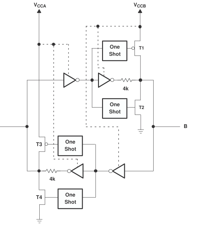
In this schematic diagram, when the VCCB outputs a high level, T1 conducts. What is the current loop of the internal 4K resistor, and why is it recommended to pull up or down resistors above 50K.
The one-short transistors T1/T2/T3/T4 are active only for a few nanosecond to speed up output edges.
When the B side outputs a high level, only the buffer behind the 4 kΩ resistor drives high, and T1 is disabled.
The 4 kΩ resistor allows other devices on the B side to override the voltage. A pull-up/-down resistor that is stronger than 50 kΩ might prevent the weak buffer from outputting a valid voltage.
Hi Li,
T1 and T2 helps the level shifter to drive the transition edges faster when a change in logic state is sensed at the input side. During a DC state (logic high/ low), the buffer loop and the internal 4kΩ series resistors are driving the I/O to hold the desired logic state. To prevent heightened VOLs and lowered VOH levels, weak pullups/ pulldowns are advised to not contend with the internal 4kΩ series resistors.
Regards,
Jack
I’ve sketched out the signal flow briefly. When a high-level signal is fed into Port B, the signal path highlighted in yellow routes this high level out to Port A while triggering a self-latching sequence to hold its own output at high state.
The green-path circuitry accelerates fast rising edge during signal transitions. All transistors T1~T4 turn off under steady-state conditions. With this topology, applying a high to Port B pulls both Port A and Port B up via the 4k pull-up resistors; to pull the logic low externally, a pull-down resistor greater than 50kΩ is required.
By the same principle, if either port outputs a low level, both ports are effectively pulled down through the 4k resistors, requiring an external pull-up resistor larger than 50kΩ to drive the signal high. Is my understanding correct?

Hi Li,
The requirements for the external pullups/pulldowns are to ensure that the voltage divider network is not formed with the internal 4kohm series resistors. Please refer to the app once blow for more information and its effects.
https://www.ti.com/lit/an/scea054a/scea054a.pdf?ts=1780695575791
Regards,
Jack