This thread has been locked.

If you have a related question, please click the "Ask a related question" button in the top right corner. The newly created question will be automatically linked to this question.

CD4047B: Recommended values for R and C

Part Number: CD4047B
Other Parts Discussed in Thread: TPLD2001, SN74HCU04

Dear Expert,

We are designing to use CD4047 Astable mode Q output at 278KHz. When we use R=8.2K ohm and C=100pf, the theoretical output Q is 278KHz. However, we found that Q is 231KHz in actual testing. When we replace it with higher precision resistors and capacitors, the frequency does not change much; We suspect that the deviation is caused by parasitic capacitance inside the chip, but I did not see the parameters of parasitic capacitance in the specification sheet;
We would like to know the recommended values for R and C in Astable mode  operating mode; What are the factors that affect the output frequency?
Thanks

  • Hi Colin,

    Thank you for reaching out! You are correct in suspecting that parasitic capacitance is playing a role, but at this frequency, there is an even larger factor at play: the internal propagation delay of the legacy CMOS architecture.

    Because the CD4047B is a classic, decades-old device, pushing it near 300 kHz highlights some of its fundamental physical bottlenecks. Let's break down exactly why you are seeing 231kHz instead of the theoretical 278kHz, and look at your options moving forward.

    1. Why You Are Seeing the Frequency Deviation

    The standard formula, f = 1/(4.40RC), assumes that the chip's internal logic gates flip instantaneously (which is basically true at very low frequencies). At higher frequencies, two hardware realities skew this math:

    Internal Input Capacitance (C_IN): The datasheet notes that the typical input capacitance is 5 pF (and can be up to 7.7 pF). When using a small 100 pF external timing capacitor, this internal capacitance—plus another 5 to 10 pF of stray PCB trace capacitance—adds directly in parallel. This tricks the chip into acting as if your capacitor is actually ~115pF.

    Propagation Delay (t_PHL, t_PLH): This is the main bottleneck. At a standard supply voltage of V_DD = 10V, the internal propagation delay from the astable inputs to the Q output is typically 225ns (and can be up to 450ns). At V_DD = 5V, it stretches to a massive 500ns typical. Every half-cycle, the chip takes an extra couple hundred nanoseconds just to process the transition and flip the output, which permanently stretches the total clock period and caps your maximum frequency.

    2. Datasheet Component Limitations

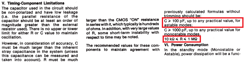
    To achieve the best stability and line up with the theoretical formulas without manual calibration, the datasheet outlines strict parameters for the RC network on page 7:

    The timing capacitor (C): Must be ≥ 100pF. However, using exactly 100pF pushes right against the boundary where stray system capacitance skews the math.

    The timing resistor (R): Must be between 10kΩ and 1MΩ. Your current value of 8.2kΩ falls below the recommended minimum. Dropping below 10kΩ forces the chip to drive too much current through the internal RC common node, distorting the internal switching thresholds V_TR.

    3. Your Recommended Options Moving Forward

    Option A: Migrate to a Modern Timing Solution
    If high-precision frequency stability is crucial for production, we highly recommend swapping this legacy part for a modern silicon oscillator or a dedicated high-speed timer variant. Newer solutions are not bottlenecked by 1970s propagation delays and can easily handle a 278kHz clock seamlessly. For one example, the TPLD2001 can be easily configured for 278kHz output with 5% accuracy and no external timing components. Another option would be to configure a 3-inverter oscillator with something like SN74HCU04 using external timing components with accuracy primarily derived from the external timing components - very similar to using the CD4047B, but with more modern process and reduced delays. A third solution could be to use a crystal oscillator and divider to get the exact frequency you want, but I expect that will be overkill in most applications.

    Option B: Try to make the CD4047B work

    Note that this will be outside the recommended operating range from TI, so we cannot guarantee reliable operation.

    If you must stick with the CD4047B, you will need to abandon the pure theoretical formula. You can scale down your resistor value (or use a potentiometer) to "overclock" the RC network, effectively forcing the lagging chip to switch fast enough to hit exactly 278 kHz. This will be best done on the bench by trial and error.

    I hope this helps clarify what you're seeing on the bench!