TXS0108E: TXS Level Translator used for DDC lines of HDMI causing issue

Part Number: TXS0108E
Other Parts Discussed in Thread: TXS0102, LSF0102

Hi Team,

I am using TXS0102DCUR and TXS0108ERGYR for DDC lines of HDMI.
I am facing issue is DDC line in RX Side when i connect the laptop. Is this because there are two TXS Series Level Translator in bwteen.
I have also attached the path in schematics for review.
The DDC Path: Laptop -> Connector -> TSX0102DCUR -> Switch IC -> TXS0108E -> FPGA
Please kindly review and let me know.

DESIGN1.pdf 

Regards,
Irfan

  • Hi Irfan,

    What is the voltage set at VCCA? Are there any waveforms that can be provided to show the anomaly observed? Please note that the internal pullups on both the TXS0108E and TXS0102 will form a parallel resistor network and result in heightened VOL. If the input low voltage is high enough, it can likely cause the one-shots to unintentionally mistrigger and lead to false logic high states (however waveforms can help confirm if this is truly the concern). 

    Regards,

    Jack

  • Hi Jack,

    There is no external pull ups provided though.
    VCCA is 1.8V for TXS0108.

    Also, I am unable to attach the wave form of working and non-working case which we have captured in saleae.


    Above is the 4K and 1080- laptop captured images. 

    The VCCA of the TXS0108E is 1.8 V, while VCCB is 3.3 V.

    The DDC path is:
    HDMI source → TXS0102DCUR → PI3WVR14412Q2ZLCEX → TXS0108ERGYR → FPGA.

    We observed that a 4K laptop detects the HDMI sink, whereas a 1080p laptop does not. We have measured the DC HIGH levels as approximately 5 V on the HDMI side, 3.3 V on the intermediate side, and 1.8 V on the FPGA side.

    We will measure the VOL on both SDA and SCL at each stage during the DDC transaction, particularly during the ACK period, and provide the waveforms for comparison.

    Please let us know if there is a recommended way to evaluate the interaction between the TXS0102 and TXS0108E internal pull-ups in this cascaded configuration.

    Regards,
    Irfan

    Below is the attached Saleae captured log with analog enabled for high and low with working and non working case

    Testing.zip

  • Hi Irfan,

    Please provide the waveforms via oscilloscope if possible (the logic analyzer will not provide the full characteristics of the waveforms). What is the operating data rate of the signals? 

    Here is an app note for best practices with designing in the TXS devices: 

    www.ti.com/.../scea135.pdf


    Regards,

    Jack

  • Hi Jack,

    I think the oscilloscope wont be able to capture the entire waveform, cause the EDID transaction takes a lots of data transmisiion.
    The operating data rate of the signal is 100KHz to 400KHz.

    Regards,
    Irfan

  • Hi Irfan,

    No worries-even a portion of the signals can be provided to get glimpse of the signal integrity.

    Regards,

    Jack

  • Hi Jack,

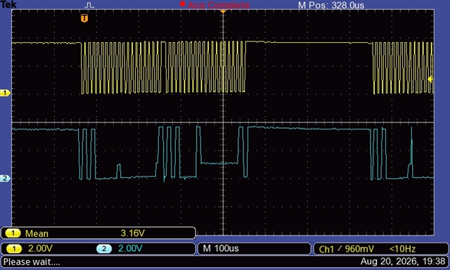
    I have attached the image of working below,

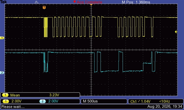
    And below is the non-working case,

    Regards,
    Irfan

  • Hi Irfan,

    I do not see any glaring differences between working/ non-working waveforms. Could you help confirm? (Even with the working waveform, it seems that a glitch is also visible). If we want to move away with the one-shots that are driving the strong transients during edges, the LSF0102 can also be eval. in place of the TXS0102, however external pullups would be needed. 

    Regards,

    Jack