SN54AC00-SP: CFP Package Forming

Part Number: SN54AC00-SP
Other Parts Discussed in Thread: LM139AQML-SP, SN54AC74-SP

The Part# SN54AC00-SP (5962R8754903VDA) it comes with CFP(W) 14 pin package, I want to form this package into gullwing type pins for the PCB placement. How can I do that, is there anyy standards to be followed while doing this operation.  image.png
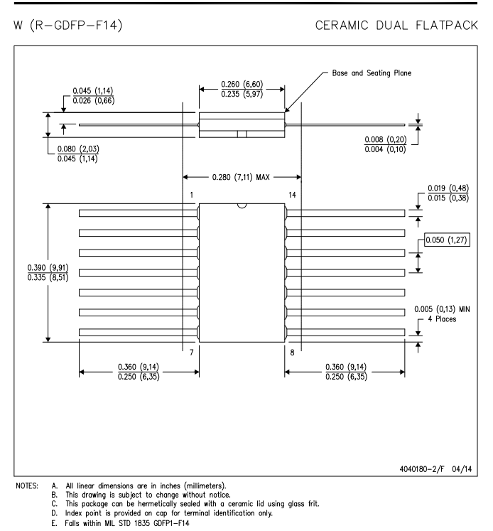
Could you provide the required details at the earliest. It will help full to proceed further.

Thanks & Regards,

Sridhar

  • To form unformed Ceramic Flatpack (CFP) straight leads like the ones on the SN54AC00-SP (5962R8754903VDA) into gullwing configurations for surface mount PCB placement, you should use precise mechanical specialized tooling rather than doing it manually. Because this component is an aerospace-grade, radiation-hardened device, standard industry regulations apply strictly to avoid stress on the hermetic ceramic-to-metal seals. We don't have the detailed step by step instruction on it. 

  • Hi Chen,

    Thank you for your response.

    We are planning to use mechanical fixtures for lead forming instead of manual forming. Could you please help clarify the following points?

    1. The permissible lead bend radius and the minimum distance from the ceramic package body.
    2. Lead-form dimensions, including foot length, stand-off height, and final lead pitch.
    3. Permissible lead coplanarity and dimensional tolerances after forming.

    Additionally, we have developed the footprint for this component based on our design requirements. Could you please review and provide the details with respect to the our footprint to from the leads.

    Your guidance will help us finalize the mechanical fixture design and ensure compliance with the component requirements.

  • For the space-grade SN54AC00-SP in the hermetic 14-pin Ceramic Flatpack (CFP / "W" Package), lead forming operations adhere to aerospace standards such as MIL-STD-883 (Method 2004) and IPC-J-STD-001 / IPC-A-610 Class 3. 

    1. Permissible Lead Bend Radius & Minimum Distance
    • Minimum Distance from Ceramic Body: Bends must begin at a minimum distance of 0.030 inches (0.76 mm) from the edge of the glass meniscus/ceramic body. The tool must clamp this unbent region securely to isolate the hermetic seals from stress. 
    • Permissible Lead Bend Radius: The internal radius of any bend must not be less than 1.0 to 1.5 times the nominal lead thickness. Given the standard lead thickness of the W-package (~0.004 to 0.006 inches), a minimum bend radius of 0.010 inches (0.25 mm) is generally required to avoid micro-cracking of the Kovar base metal or damage to the gold/solder plating. 
    2. Lead-Form Dimensions (Gull-Wing Profile)
    When using mechanical fixtures to shape the flat leads into a surface-mount gull-wing configuration, the standard target dimensions are governed by board-level clearance requirements:
    Lead-Form Parameter Recommended Guideline / Standard Dimension
    Foot Length 0.040 inches to 0.060 inches (1.02 mm to 1.52 mm). This provides a reliable solder fillet footprint according to IPC Class 3 specs.
    Stand-off Height 0.010 inches to 0.020 inches (0.25 mm to 0.51 mm). This ensures sufficient spacing beneath the ceramic package for post-solder cleaning and thermal expansion relief.
    Final Lead Pitch 0.050 inches (1.27 mm). The mechanical fixture must maintain this native unformed center-to-center pitch with high parallel alignment.
    3. Permissible Coplanarity & Dimensional Tolerances
    • Lead Coplanarity: The maximum permissible coplanarity variance across all 14 leads after mechanical forming is 0.004 inches (0.10 mm) max. For optimal manufacturing yields on high-density space flight boards, a tighter budget of 0.003 inches (0.076 mm) is highly recommended.
    • Dimensional Tolerances:
      • Foot Angle (Seating Plan): Typically 0° to 5° relative to the PCB plane.
      • Linear Dimensions (Foot length/Stand-off): ±0.005 inches (±0.13 mm).

  • Hi Chen,

    Thanks for your detailed answer. 

    Could you confirm, this same standards can be applicable across all the space grade components like - LM139AQML-SP, SN54AC74-SP, etc..

    Regards,

    Sridhar R

  • Yes, as long as they use the same package, they should share the same standard.