This thread has been locked.

If you have a related question, please click the "Ask a related question" button in the top right corner. The newly created question will be automatically linked to this question.

Interface to oscillator

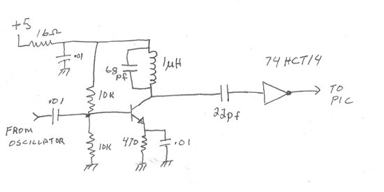
I need to interface a microprocessor input to the output of a 16 - 20 Mhz oscillator. The output of the oscillator can be as high as 7.5 v p-p or down to 3 volts p-p all sitting on a 4.5 volt level. I am coupling to the oscillator with a 22 pf cap which at 18 Mhz is around 400 ohms. The spec from the datasheet is +/- 20 ma for the clamp current. I used 7.5 volts and the impedance of the cap and come out to 18 ma peak.

Is it okay to couple this way using the internal clamp diodes or should i do it a different way. If not a good way what would be a better way

Thanks

Geof

  • Geof,


        That might be a little "iffy" at the lower (3V p-p) oscillator swing.

        I'm not sure if the HCT has a diode to Vcc on the inputs.  It might have something more like a Zener to ground with a breakdown in the 8V to 12V range.  You could check it out using a curve tracer, but in general it is best not to "design in" these internal clamp diodes.  They may change with chip revisions and you would not know it because they are not on the datasheet.

        What you have is the HCT input floating in a DC sense, so who knows at what level it will be.  I think adding a resistor from HCT14 output to HCT14 input to hold the DC input voltage near the switching threshold would make things more stabile.  I'm guessing a 10K to 100K resistor would be fine.

        Hmmm... Then the Schmitt trigger action might interfere with proper operation.  Perhaps a resistive divider on the input (one resistor to ground, another to Vcc) would be better.  Set the DC level of the divider halfway between the input hysteresis levels.


    -Steve