This thread has been locked.

If you have a related question, please click the "Ask a related question" button in the top right corner. The newly created question will be automatically linked to this question.

TXB0102 driven from opto-coupler

Other Parts Discussed in Thread: TXB0102, TXS0102, SN74LVC2T45, SN74AVC2T244

7418.Design1.pdf

Hi,

Attached is the schematic used to drive TXB0102 part.

Opto-coupler is driven from unit 1, the output is connected at input of TXB0102 with cable length of 7 metres.

Issue Faced:

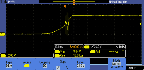
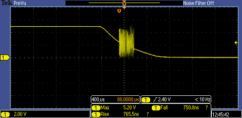
Without load (TXB0102), signal driven from opto is properly toggling to 0 and 1. But when load is provided, signal toggling is not proper i.e, while signal rise from 0 to 1 lot of noise is appearing.

Please suugest how to drive TXB0102 using open drain circuit.

Regards,

Mani

  • Hi, Mani

     Could you post some pictures to show input and output signal when the noise happen. It will provide a lot help to analyze this case.

    If open drain circuits are necessary,  the TXS0102 might be a better option. Because TXB0102 have low
    dc drive strength.

    Thanks

    Lawrence

  • Hello Lawrence,

    Sorry for delay in response.

    Please find below snapshots captured at the output of opto-coupler. Please let us know your suggestions on fine tuning the circuit..

  • Hi

    Is there any load circuit at output of TXB0102?  If yes, could you provide specific parameters and power-up sequence?

    Best,

    Lawrence

  • Hi Lawrence,

    TXB0102 is connected to Virtex-5 FPGA I/O. Power-up sequence is not there for 3.3v and 5V.

    After the unit is stable, then only we have initiated toggling of "0" and "1"..

    Kindly note that captured waveforms are at input of TXB0102.

    Regards,

    Mani

  • Hello Lawrence,

    One more observation that we made was with pull up R3 changed from 1K to 50 ohm provided better results(Same rise and fall time images provided earlier).

    Please let us know your inputs..

    Regards,
    Mani

  • Hi, Mani

    Sorry for unclear description. I want to know whether the signal source is PVDZ172N. If yes, the input is B1.

    Did  the snapshots captured at B1?

    If it is possible, please maka a testing case that enhancing the frequcecy of input singal at B1 and obseving the signal.

    Thanks

    Lawrence

  • Hello Lawrence,

    Signal source is PVDZ172N and input is B1.

    Snapshots are captured at B1 only.

    Presently observations are made "0" and "1"by using the external switch.

    Please let me know is the issue clear..

    Regards,

    Mani

  • Hi, Mani

    For TXB0102, there is reqirement on input transition rise or fall rate. The maximum of its value is 40ns/V (on page 3 at TXB0102 datasheet).

    From your testing snapshot, the input rise rate is out of range of TXB0102 spec.

    TXS0102  is suitable option for your application.

    Thanks.

    Lawrence

  • Hello Lawrence,

    Thanks for your reply,

    We have replaced TXB0102 with TXS0102 device, Still there is problem with risetime (Observations are same as TXB0102).

    Can you please let me know is there any alternates / replacements available for TXS0102DCUR.

    Regards,

    Mani

  • Hi, Mani

    The possible reason is the photovoltaic relay turn-on time. The long turn-on time will result in long rising edge of TXS0102 and the direction sensing function will not work well.

    Could you zoom into the input rising edge and compare it with output rising edge ?  

    Please add some capacitor load on output node and observe the waveform of the input and output.

    I am looking for some part which meets the rising edge requirement. I will let you know ASAP if I get it.

    Regards,

    Lawrence

  • Hi Mani,

    Looking into your discussion with Lawrance, I observe that you are trying to transmit a logic signal to a distance of 7m, to avoid reducing its strength you are using it open drain.

    I feel you should try the protocols say RS422, RS485 which are basically used for long distance and multidrop communication channel. An even you can directly use drivers which are galvanically isolated avoiding the use of optocouplers.

    Regards

    -Anand 

  • Hi, Mani

    The TI auto-direction voltage translators, TXB serial and TXS serial, have requirement on input rise rate. If rising time is too long the glitch can be occurred at rising edge.

    The SN74LVC2T45, direction-control voltage translator, might be a choice part in your system. But there is no hysteresis function in SN74LVC2T45. Thus it is sensitive to external noise if input signal has long rising time. Then, the glitch may be occurred at output when input is noisy at comparison threshold voltage.

    The SN74AVC2T244 is with hysteresis function. But its operating voltage is from 0.9 to 3.6V on both sides. If the opto can work at 3.3V, SN74AVC2T244 is a suitable part in your system.

     BR

    Lawrence