This thread has been locked.

If you have a related question, please click the "Ask a related question" button in the top right corner. The newly created question will be automatically linked to this question.

TXB0101DCKR not function well

Other Parts Discussed in Thread: TXB0101, TXS0101

Hi,

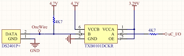
Actually i'm using this IC for Onewire bus driver. 

I'm first time using this IC. It seen like easy to use but it doesn't work for me and i have use scope to check the input output waveform. The waveform as bellow:

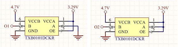
O1 waveform when input Pin-3 is Low:

   - W1: Pin-3 waveform:

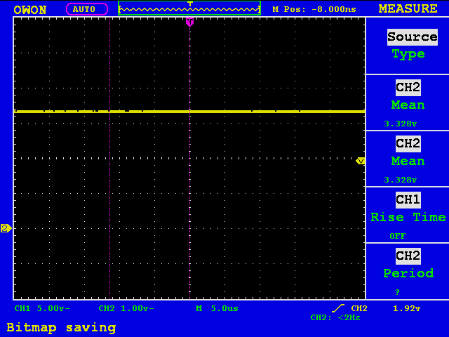
   - W2: Pin-4 waveform: "When input is low the output pin-4 is not 0Volt but is around 2Volt"

O2 waveform when input Pin-3 is High:

   - W3: Pin-3 waveform:

   - W4: Pin-4 waveform:

W5: Ch-1 Input pin-3; Ch-2 Output pin-4

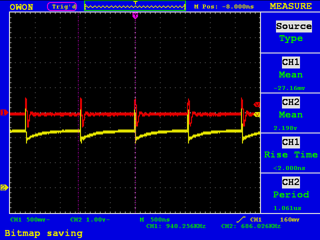
Anything wrong with the circuit connection? and I still wonder why the signal waveform is not a linear line.

Is it this IC it not suitable for Onewire bus driver? Can anyone please give some advice? Thank you.

  • Hi, Tang

    According to the snapshot, when high level signal transition TXB0101 worked well and when low level signal transition the problem came out.

    The settling process and periodic signal can be observed on the snapshot when low level signal is transferred. For TXB0101, there is a 4k resistor at output port.  If there is a pull-up external resistor R, the Vol will be different with GND potential and introduce settling. Please check the resistance on O1 net. As for periodic signal, could you just check O1 net without TXB0101 if ground potential is fine?  

    Could you provide more output load circuit information of TXB0101? It will provide help to analyze the problem accurately.

    BR

    Lawrence

  • Hello Lawrence,

    Thanks for your reply.

    Ya, from the TXB0101 datasheet shown 4K resistor at output port. Yes, i have connect a pull-up external resistor 4k7 Ohm. At this moment, this TXB0101 will only drive one device DS2401 this device is OneWire interface. For this device request a external pull-up resistor, you can also check this device from the datasheet.

    In the earlier in between input pin-3 and uC_I/O i have put a 4k7 resister but now i removed it. uC_I/O signal direct input to Pin-3.

      could you just check O1 net without TXB0101 if ground potential is fine?  

    I haven't check the ground without the TXB0101 yet because I need to un-solder the TXB0101. But i did check all the pin connection in good condition.

    Thank you,

    Tang

  • Hi, Tang

    There is an inside 4K resistor at both A and B port in TXB0101. If the external pull up resistor is necessary, its value should be more 50kΩ. If the output port external pull-up resistor value is 4.7k, the output low level voltage value will equal to 4*VccB/(4+4.7).

    In your design, the DS2401 data pin is open-drain port. The pull-up resistor range is from 1.5kΩ to 5kΩ. Thus, TXS0101 is more suitable in your system.  It is ideal for use as open-drain driver.

    Thanks

    Lawrence

  • Hello Lawrence,

    Sorry for late reply.

    The formula can prove the practical result. At this moment i don't have 47K, 50K or 100K to replace the external pull-up resistor value 4.7k. 

    I have request a few TXS0101 sample unit for testing. For this TXS0101 have internal pull-up resister value is 10k. So i should connect a external pull-up resistor 4.7k which mean parallel with internal pull-up resister 10k will become ~3.2k value. So the resistance value still within the range 1.5kΩ to 5kΩ. Am i rite?

    For the input side pin-3 should i connect external pull-up resister? What if i don't pull-up the signal will cause any problem?

    I will test again when the sample unit is arrive.

    Thank you,

    Tang

  • Hello Lawrence, it work fine after replace TXB0101 to TXS0101. Thanks ;)