Hi,
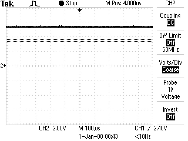
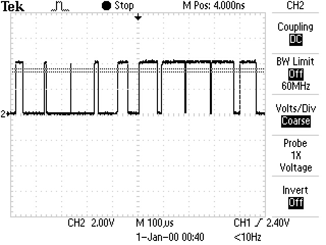
I'm working on a design that involves a PWM signal with a carrier frequency of ~1-3MHz 0 and 5V and I've been trying to use the SN74LVC2GU04 to invert the signal. I've scoped the input to the SN74LVC2GU04 inverter, and the PWM signal I've created is being delivered correctly, but the output from the inverter is railing high at 5V. I can't see any portion of the input signal in the output and I'm concerned I might have blown the inverter. Is this an accurate diagnosis or is there another problem that I'm missing. I was wondering if the input to the inverter has an internal pull-down resistor on it that might be making it act this way. Any help would be greatly appreciated.
Thanks!!!
Inverter Input:
Inverter Output: