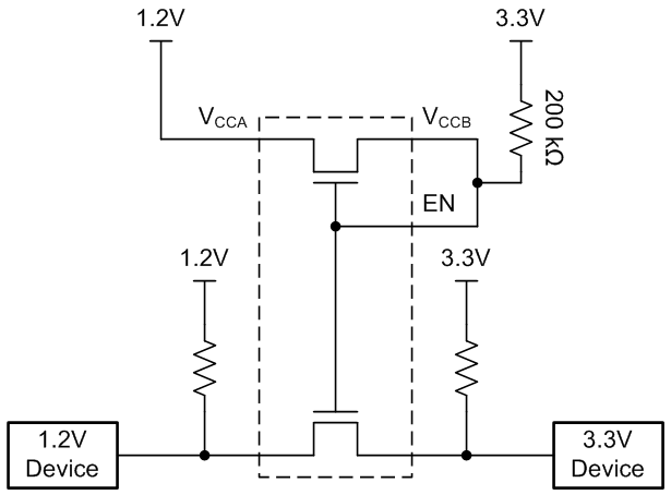
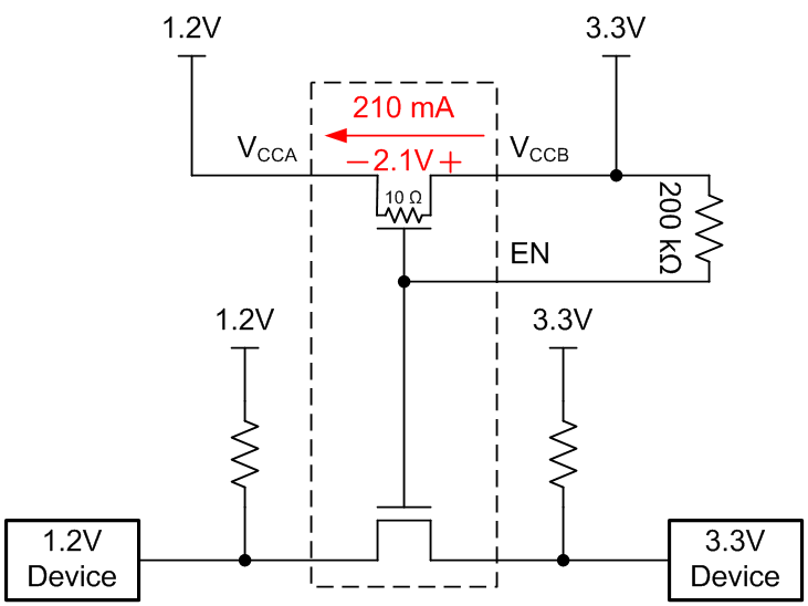
i want to turn on two of led. can i use it this way with no problem?
especially, is there any problem with directly connect voltage and VCCA pin?
This thread has been locked.
If you have a related question, please click the "Ask a related question" button in the top right corner. The newly created question will be automatically linked to this question.
Hello,
I assume that your goal is to power the LED circuits with 3.3V via up-translation. Please correct me if I am wrong in this assumption.
The 200kohm pull-up should be between VCC_3.3V and both pins 7 and 8 (See Figure 6 in the datasheet. Right now VCCB is tied directly to VCC_3.3V, which will not work properly.
It might help you for me to explain how this part works. When an input on the low side goes high, the FET on that channels turns OFF, which produces a HIGH-Z output on that channel. Since the output is no longer connected to the input, the pull-up resistor takes over and the output goes up to the pull-up voltage. This means that all of the drive current for your LED goes through the pull-up resistors, and none of it goes through the part.
I think you can use R13 and R14 as pullups, connecting them directly to 3.3V. When the A2 input goes low, the D2 diode will be forced low and turn off. I am a little curious - why is D1 connected through the LSF? It appears to be always on.
This is my recommendation on the schematic:
Hi Andrew,
The short answer is that the amount of current produced will likely destroy the device. The long answer follows.
When the bias circuitry is connected correctly, there is about 10 uA (3.3V - 1.2V = 2.1V; 2.1V/200kohm ~= 10uA) of current constantly being pulled through the reference FET in order to turn on the device and produce the correct voltage on the gates of all the fets inside the device. This image shows the correct connections:
Note that the 200kohm resistor is in series with the channel of the device, so the total resistance from the 3.3V source to the 1.2V source is about 200kohm. Also, note that the majority of the voltage will be dropped across that 200kohm resistor, so there will be a very small voltage across the FET producing a gate voltage very close to the lower voltage - which is important to make this device operate correctly.
Now, if you were to connect the device incorrectly as shown below:
For starters, the amount of current produced would likely destroy the device very quickly (the absolute max channel current is 128mA). Even if it did not, the voltage on the gates would be 3.3V, which would not allow the device to operate as intended.