This thread has been locked.

If you have a related question, please click the "Ask a related question" button in the top right corner. The newly created question will be automatically linked to this question.

LSF0204 pull-up resistor

Hi,

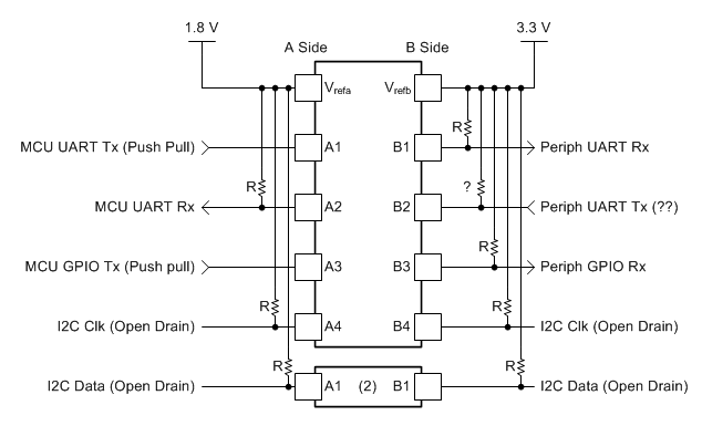
could you please clarify where I (must) need to put pull-up resistor??

 only case 4 is bi-directional.

  1. MCU UART Tx(Push pull) --> LSF0204RUTR A side --> LSF0204RUTR B side --> Peripheral UART Rx
  2. MCU UART Rx <-- LSF0204RUTR A side <-- LSF0204RUTR B side <-- Peripheral UART Tx 
  3. MCU GPIO Tx(Push pull) --> LSF0204RUTR A side --> LSF0204RUTR B side --> Peripheral GPIO Rx
  4. MCU I2C Data <--> LSF0204RUTR A side <--> LSF0204RUTR B side <--> Peripheral I2C Data
  5. MCU I2C Clock --> LSF0204RUTR A side --> LSF0204RUTR B side --> Peripheral I2C Clock

 please let me know each side, A,B whether pullup resistor is needed or not.

and if there's no need to use pullup resistor, then should I just tie the pin with Vcc directly? or GND? or Open?

Thanks!

  • Hi Emkay,

    Please take a look at the "Frequently Asked Questions" section of this application report.  There is a very good summary there of exactly when and where pull-up resistors are required with the LSF family of level translators.

  • Hi Maier,

    I've already looked into it, and talked with apps ppl before.
    I'm trying to get confirmation on this, whether I understood correctly or not.
    please give me answers of my questions, and it will help me a lot.
    this is quite urgent issue.

    Thanks.
  • I will need voltage levels for each side of the LSF, as well as current drive to/from each device (including input leakage currents) to recommend pull-up sizes.
  • Thanks Maier,

    A side : 1.8V
    B side : 3.3V
    current drive : will talk to customer and recommend 300ohm to 1kohm , not to let the current over than 15mA.

    Thanks!
  • "if there's no need to use pullup resistor, then should I just tie the pin with Vcc directly? or GND? or Open?"

    None of those -- if a pullup is not required, the device is connected directly to the input or output.  That is all.  Once I have a better idea of your system, I will make a schematic to help you visualize the system.

  • Emkay,

    I have built a schematic to show where pull-ups are required.  There is a ? on the UART return line's high-side pullup.  Since I do not know the output type of the Peripheral UART Tx, I cannot make a recommendation.

    ? - If the device is push-pull, a high-side pull-up is not required.  If the device is open-drain or open-collector, a pull-up is required.


    The simple rules to follow:

    1. An open drain connection will ALWAYS require a pull-up and a push-pull will never require a pull-up.

    2. A passive receive on the LOW side will not require a pull-up (unless it has significant leakage current) and a passive receive ont he HIGH side will always require a pull-up.

  • Maier,

    Thanks for your sincere reply, it helped me to confirm the application note.

    on the A2 side, it's Low side and recevier, so that there's no pull up needed, right?
    in the application note, if there's signal integrity(noise problem), then pull up can cover it, but it's not mendatory. correct?
  • That's right -- I would keep it just to be safe.