


Problem:
When we first hook-up a multi-board system using a TXS0102 to level shift an I2C bus between the boards, a critical failure will occur causing the TXS0102 to blow-up, but only on 1 system in 25.
Background:
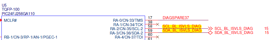
We are utilizing a TXS0102 as a +3.3VDC to +5.0VDC translator for multi-board I2C communications bus. There are 3 devices on the +3.3VDC side (VCCA) including the master micro-controller and 1 device on the +5.0VDC side (VCCB).
The VCCA side is power from the same rail as the micro-controller and has a 4.75k pull-up on each data line; the +3.3VDC rail will always be powered up completely before the VCCB rail is enabled. The regulator powering the TXS0102 VCCB rail is located on the same board as all of the VCCA components. The OE pin is shorted to ground causing the device to be always on.
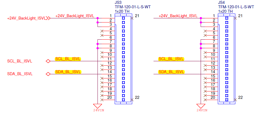
The VCCB device is a slave micro-controller that is located on the second board. It is powered by it's own +5.0VDC power rail and each data line has a 4.75k pull-up. The power going to this slave board is controlled by the master micro-controller and comes on at roughly the same time as the +5.0VDC regulator powering the VCCB rail. The connection between the boards is a redundant connection scheme meaning that each signal has two parallel wires.
Failure Description:
The actual failure occurs on the initial power-up of a slave board in a dedicated test jig. Excluding the I2C communications bus, each slave board is functionally tested at the assembly house and then verified by manufacturing prior to inserting it into the test jig. (The test jig is a full-system platform with dedicated hardware used only for confirming the slave board's I2C bus.) When power is first applied to the jig, the master micro-controller performs a self-check and then enables the peripheral rails; this is when the actual damage to the TXS0102 chip occurs. Replacing the TXS0102 chip will repair the jig and allow it to test the next board, but I do not have data on f the same slave board will blow the TXS0102 a second time. The boards are all quarantined and given to engineering for analysis. Initial checks of the board showed nothing amiss with the I2C signals, but 1 did have to have the slave micro-controller replaced which fixed it.
Question:
What types of problems would blow up the chip on such an infrequent basis?


