Hi,
We are tring to use LSF0102 to translate both 2V and 5V pulse wave to 3.3V pulse wave, but it does not work as expected.
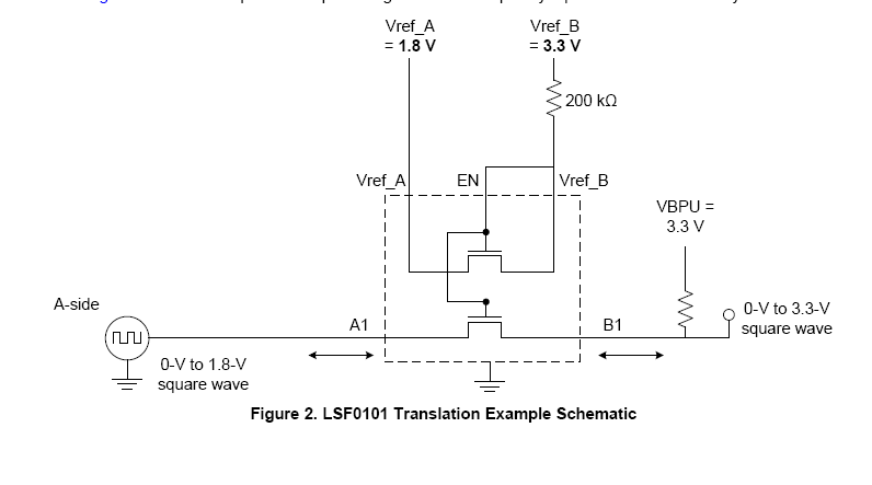
The schematic we use is similar to fig.2 of slva675b,Vref_A=1.8V and Vref_B=VBPU=3.3V, A1 and A2 are inputs, B1 and B2 are outputs, no pull-up resistors on A side and 360ohm pull-up resistor on B side.
The results are shown below
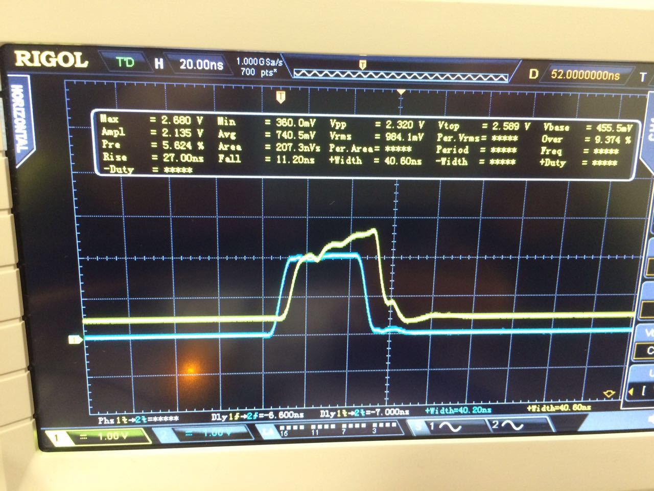
(1) Input (blue): Pulse wave Vpp=2V, pulse width = 40ns(application requires such narrow width),rising edge=5ns
Output (yellow): low-volatage=0.4V and high-voltage=2.6V, The high-voltage can go up to 3.3V only if pulse width > 120ns
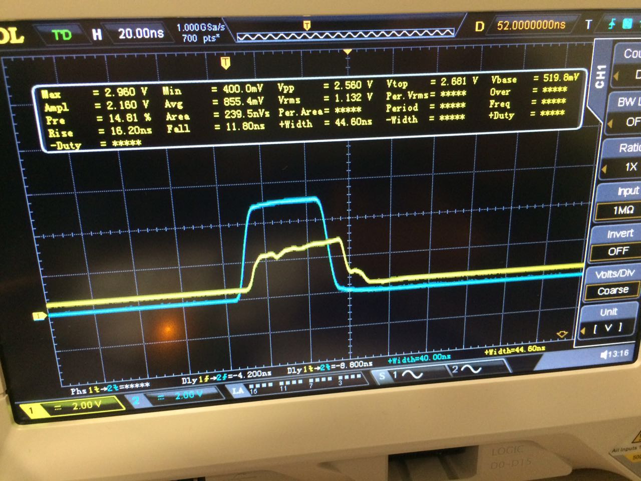
(2) Input (blue): Pulse wave Vpp=5V, pulse width = 40ns(application requires such narrow width),rising edge=5ns
Output (yellow): low-volatage=0.4V and high-voltage=2.9V, The high-voltage can go up to 3.3V only if pulse width > 100ns
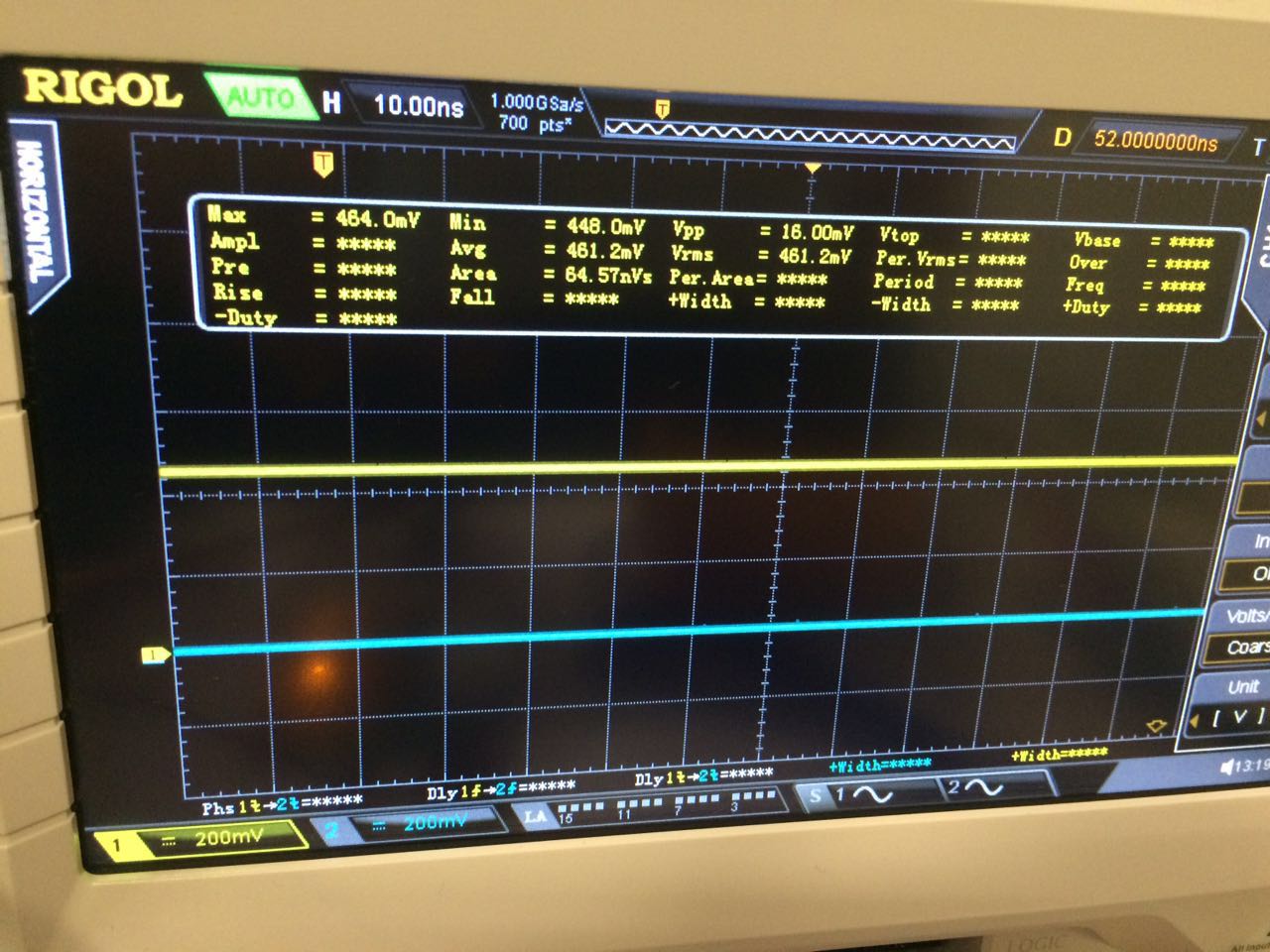
(3) Input (blue): 0V DC
Output (yellow): 0.45V DC
My questions:
(1) Why is the low output is about 0.4V, is it the right result or something wrong with our schematic?
(2) Can we get a 3.3V high output with a 40ns width pulse wave input and how?
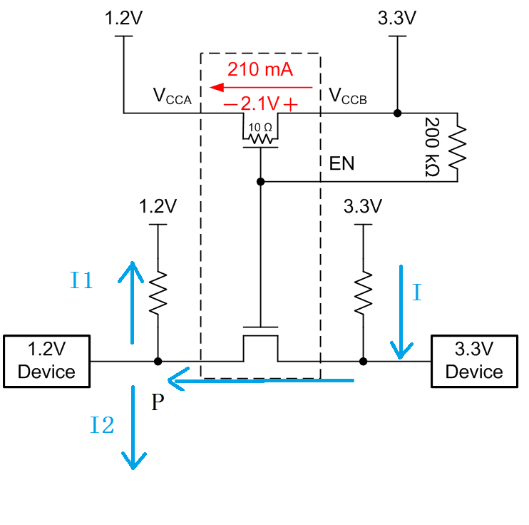
(3) Is pull-up resistor on A side needed? I am confused because there is no pull-up resistor in fig.2 of slva675b, however in this post

pull-up resistor is needed.
Regards,
Eric