This thread has been locked.

If you have a related question, please click the "Ask a related question" button in the top right corner. The newly created question will be automatically linked to this question.

The design of CD74HC4046A in 0~200Hz freq. band

Hi BU team

One customer wanted to generated a VCO with 0~200Hz under a 256 divider.

below is the schematic for your reference.

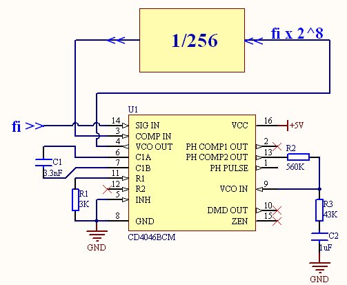
when R1=100kohm, the output was 20~130kHz.when R1=200kohm, the output was 11Hz~70kHz.

Would you share a workable design for the 0Hz(as low as 0)~200Hz?

Thanks

  • Hi Ted ,

    I am unsure of this device and its behavior and design , please give me time for research and a reply .
  • Ted,

    So you want VCO 0 to 200Hz for an output of 0Hz to 51.2kHz.

    Your results so far are actually good. For R1=100k you had a 6.5:1 range and at R1=200k you had a 6.4:1 range.
    To get 200Hz to 0Hz VCO range requires an infinite MAX/MIN range.

    To get a wider range, I would suggest something that sets the VCO center frequency close to the input frequency.

    My first thought is to convert input frequency to a sink current and replace R1 with that sink current.
    If done correctly the center VCO will track 'fi' and the loop should lock fine.
    At some low frequency C2 may need to be increased.

    A much wider range should be achievable but there may be no way to get all the way to zero.