This thread has been locked.

If you have a related question, please click the "Ask a related question" button in the top right corner. The newly created question will be automatically linked to this question.

Birectional buffer recommendation

Expert 1105 points
Other Parts Discussed in Thread: CD74HC243, CD74HCT243, TXB0101

Hello,


I have a design where multiple cards are connected with a cable. I use a SN74LVC1G34DBVR in each PCB to buffer a control signal ( TTL )

---->  Control Card 1 ----->  Control Card 2  --------> Control Card 3

             SN74LVC                   SN74LVC                         SN74LVC

From the design review, a request came,  "We want to users to connect control cards without paying attention to IN / OUT direction.  So I need an IC with auto direction sensing or some other method.


Can you please guide me for a possible logic IC or another method.

Thanks a lot

rifo

  • Hi Rifo ,

    You mention that the signals are TTL , and LVC are not TTL compliant inputs .
    I can search for the right part, meanwhile , other performance requirements can also be helpful in narrowing down .
  • Also , to add to the above , AHCT / HCT devices are TTL compliant inputs which have Vih of around 2V .
    These signals are bidirectional I/Os? we might be looking for autodirection sensing transceivers .
  • Hello Shreyas,

    Thanks a lot for your answers. I guess I made a mistake then, I checked the datasheet of SN74LVC1G34DBVR and saw that it was oke upto 5.5V and went with that.
    About the autodirection sensing transceivers, I wasn't able to find a version that accepts 5V on both sides. Do you know a suitable part for that?
    if we don't then maybe I should consider sending out this control signal in 3.3V,

    thanks a lot
    rifo
  • Hi Rifo ,

    Alright . I have filtered our parametric search for you to determine the transceivers . They are mostly high bit width count devices .CD74HCT243 is TTL compatible , CD74HC243 works across 2 to 6V range .

    The direction control pin is not explicit but OE pin selects between the inputs / outputs and the hi-Z states .

  • Hello Shreyas,

    Then do you think I should consider a new approach? I can't really control the OE pins because I won't have the information about how many units did the user plugin to the system and which way he/she plugged in so autodirection sensing is important.

    or maybe, I should remove the buffers in each control card and drive the signal with a single buffer at the source. But then I need a buffer strong enough to drive a cable of 20meters and 50 control cards (which are plugged in to the system in a serial way)

    Source ----> Control Card ------> Control Card ------> Control Card ....
    (Strong
    Buffer)

    can you please suggest me an alternative part for this scenario Shreyas? I can lower the voltage to LVC levels if that would help us

    thanks
    rifo
  • Rifo ,

    The signals being bidirectional or unidirectional matters . you cannot have cards working if the signals are unidirectional when buffers are used and they are placed in wrong way .
    The LVC2G34 / 3G34 buffers would be strongest buffers with 32ma . If you need more drive strength , you need multiple outputs ganged together to have 64mA /96ma .
  • Hello Shreyas,

    I guess if I switch to 3.3V signals then I will be able to use TXB0101DCKR. It has autodirection sensing, and both sides can have the same voltage supply level.

    Reading the datasheet, I see that it can drive capacitive loads upto 70pF without issues and when it's larger than 70pF, the datasheet says that

    " O.S. will time-out after 10 ns and subsequently turn off before the output voltage is driven fully high or low. From there the output will continue to rise or fall based on the RC time constant determined by the 4-k Ω buffer, load resistance and capacitive loading "


    In my case, I will only be sending a high or level pulse once per second, so I believe above condition won't be an issue for me. Would you agree?

    thanks

    rifo

  • Hi Rifo ,

    This product belongs to a different product line within TI and i believe you shouldn't have problem using this . This is auto direction sensing device and Vcc shouldnt go above Vccb in any case. This belongs to voltage translation category rather than a buffer .

  • Hello,


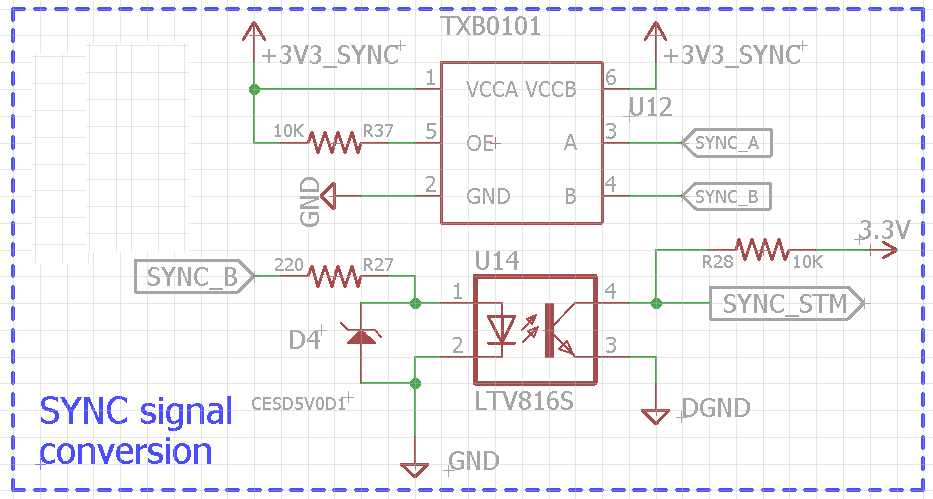
    in case it may be handy later on, I came up with the below circuit

  • rifo,

    Regarding using the TXB0101 to level transalte a pulse about once per second, what is your target pulse width? With a large capacitive load, a wide pulse width is recomended.

    For the TXB0101, keep in mind the following:

    1. To properly toggle the TXB0101 outputs, the device driving the TXB0101 inputs must be capable of sourcing and sinking at least 2 mA.
    2. The TXB0101 output levels are only guaranteed if the target device won't draw more than 20 uA of current.

    Best Regards,
    Nirav
  • Hello Nirav,


    Thanks a lot for your reply. My target pulse width is actually around 400ms, depending on the trials, I can change its value.

    In my setup, there are multiple controller boards that are serially connected to each other. Each controller board will have a TXB0101 on it to buffer and forward the sync signal so coming back to your notice,  each txb0101 will actually be driving another TXB0101

    Below is an illustration of the system

    thanks  a lot for your help

    rifo