


Dear Ti,
We are using the bi-directional level shifter TXB0108 to convert GPIO from/to a 1.8v device to/from 5v. 4 of the 8 channels are used in the direction from the 1.8V device to 5V to opto-couplers [OUTPUTS]. The other 4 channels are going from opto-couplers (emitter side 5V and pulled down) to the level shifter, to the 1.8V device [INPUTS].
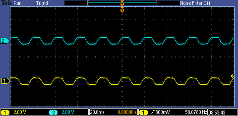
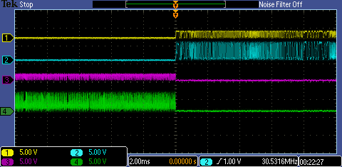
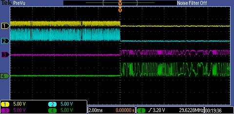
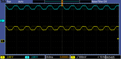
When testing the input direction we noticed a strange behavior. When an input is given to the opto-coupler and it switches, the GPIO on the 1.8V device goes high as intended. However, when releasing the input signal on the opto-coupler, the signal line on the 1.8V side stays high. We removed the opto-coupler and replaced it with a plain switch. When the switch is closed the signal on the 1.8V side goes high. When opening the switch it stays high unless I touch the signal line (5V side) with a conductor (an unconnected wire of 20cm (acting maybe as antenna)). As the datascheet mentions not to use pull downs with resistors smaller than 50k we have replaced our 10k with both 60k and no pull down at all. Both options did not solve the problem.
The outputs are working except for 1 channel (A5<->B5). When modifying the channel signal on (A6 <> B6) the signal on A5<-> B5 drops. As we have 16 I/Os in total we use two of these TXB0108 and both are showing exactly the same behavior.
The used opto-couplers are: SFH6156
Schematics are attached.
Any help would be appreciated.


