This thread has been locked.

If you have a related question, please click the "Ask a related question" button in the top right corner. The newly created question will be automatically linked to this question.

Bascule D In Toggle problem - SN74LVC1G74

Other Parts Discussed in Thread: SN74LVC1G123

Hello,

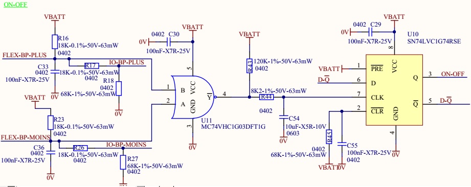
I have this schematic, the aim is to detect a simultaneous presssed push button during 1-2s. At each  simultaneous press, the ON-OFF signal toggles.

For information, push button are not represented but the first is between 0V and FLEX-BP-PLUS and the second between 0V and FLEX-BP-MOINS.

So my problem is at the first press, ON-OFF goes correctly from 0 to VBATT, but impossible to re-toggles from VBATT to 0. It seems to be that the rising edge is not detected. Thinking that could be the rise time of CLK, I tried with a small C54 value (100nF and 470nF), same result and with C43 at 10k (+C54 = 100nF) and same result. Anyhow, the datasheet says that the rise time is not important, it's the voltage level.

The detection of the simultaneous press works correctly, so U11 is OK.

Somebody would have an idea wher's the problem in my design ?

  • Hi Samuel ,

    The LVC1G74 clk input doesnt tolerate slow rising edge inputs very well . I see there is huge RC in between NAND gate to the input of flip flop .
    Is the pullup resistor required at the output of the NAND gate ? Is it open drain device ?

  • Hi,

    I'm surprised because in the datasheet I see that page 10 :

    "Clock triggering occurs at a voltage level and is not related directly to the rise time of the clock pulse."

    It's strange because in more, at the first rising edge (with this huge RC), the ON-OFF toggles to logic "1". But impossible to toggles to "0".

    Otherwise, yesterday, I tried with 100nF instead of 10uF and 10K instead of 120K, is it large still too much ?

    I believe that yesterday I tried without capacitor with no result, I will re-try.
  • I tried without capacitor and it's OK...I have difficulty to explain why it works with the first rising edge from "0" to "1" and not after...

    The main thing it's to debug so it's good, but if you have explaination about wthis behaviour...

    I forgot to answer at your last question. Yes U11 is an open-drain output. I selected this kind of output to adjust the rising edge with 120k/8K2/10uF RC. It was to toggles only with a long simultaneous press on the 2 button, around 1 to 2s instead of instantaneous toggle.
  • Hi Samuel ,

    I am glad to hear it works now . I understand your configurable delay implementation requirement for having the open drain output .

    There are configurable reset timers for push button control devices from TI as I know . not sure if this would be a good fit for your application. Also , SN74LVC1G123 is monostable multivibrator which has application for switch debounce . Please refer to the app note

  • Hello,

    For the moment I shunt the delay with the RC couple. So I deleted R43 and C54 and I replace U11 by the same version in Push-Pull output.

    I did some test today and the serie resistor R44 is very important. With a 18k resistor I have some malfunctions (double toggle with one press), With a 68K it's OK.

    Thank you,

  • Samuel ,

    If your open drain NAND gate can be replaced with Schmitt trigger NaND gate , you can save on the Vbatt power drain which is currently happening . I do not see that the pull up voltage is different from the Vcc of the NAND gate .
  • Hi,

    It's not a NAND gate (mistake from me) but a NOR gate. So I replaced it by a PushPull output to save the current consumes by the pull-up as you said.

  • ....I have another problem. When Vbatt is my laboratory supply, the ON/OFF works but when I use a LiPo battery it doesn't works. An idea on this problem ?

    U11 generates the rising edge correctly but the latch don't toggle and when I place my oscilloscope proble on the signal CLK of the latch, the latch works again...

  • I tested again with more smaller resistor (34K), it seems to be good. I'm very surprise of the sensitivity of the chip with a simple serie resistor at his CLK input. I will try to optimize the good value.

    Edit: it not depends of the supply source but it varies from board to board....