This thread has been locked.

If you have a related question, please click the "Ask a related question" button in the top right corner. The newly created question will be automatically linked to this question.

CD4047 monostable mode timing issue. incorrect and erratic timing behavior.

Hi all,

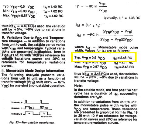
Facing problem with CD4047. As per attached ckt diagram, instead of 6-9V I am powering the CD4047 using 3.3V regulator. CD4047 is being used in  monstable mode, with RC values set to R=330K ohms and C=10uF. Theoretically i should be getting a time period (2.48 RC) as 8.14 seconds. But practically the time period was obtained to be around 15 seconds. Also on testing it repeatedly a total of 50 times, I saw that it gives a time period of around 8 seconds for 7 operations and 15 seconds for remaining 43 operations.

Kindly let me know what could be the problem in this case.

Thanks,

Roshan

  • Hey Roshan,

    Could you provide what Voltages you are putting across for pin 8 and pin 6. The Time period calculation is sensitive to the difference between pins 8 and 6 and I want to make sure that I understand everything correctly.

    Thanks,
    Daniel
  • Hi Daniel,

    Thanks for the reply.

    The voltage on pin no 8 wrt ground when giving a low to high pusle is 3.3V.
    The voltage on pin no 6 wrt ground is 0.
    The voltage across pin 8 and 6 when not triggered is 0V
    and when a low to high pulse is given the voltage across them is 3.3V.

    Thanks,
    Roshan
  • Hey Roshan,

    Vtr (Which is the voltage difference between Pin 8 and Pin 6) changes the constant of the circuit depending on what percentage of Vdd the voltage is. The listed one they have is a default one which says 2.48. This constant is found using a Vtr that is equal to half of the Vdd. Below I have the equations I got off of the data sheet on how to find tm (how long the pulse is) and t1 (how long the pulse is high). Using Vtr close to Vdd will most likely cause erratic behavior in the pulse length. I would test using a higher Vdd and if you continue to have problems come back to me and we can continue from there.

    Thanks,

    Daniel

  • Hey Daniel,

    We have increased VDD to 9V using a 9V battery and are keeping the voltage between pin 6 and 8 to 4.5V using a DC power supply. Common grounding has been done.

    Still we are facing the same issue. R=330k and C=10uF. We are now getting a time period of around 7 seconds. Sometimes the time period varies to 3-4 seconds.
     

    Kindly suggest solution for the same.

    Regards,

    Roshan

  • Hi Roshan,

    Is it possible to see a waveform of the problem you are seeing? At least one period of the 7 second period and one period of the 3 to 4 second period would do.

    Thanks,

    Daniel

  • Hi Daniel,

    Exactly waveforms from which pins would you require. The waveforms are a high pulse of 3 and 7 seconds respectively. 

    Regards,

    Roshan.

  • Hi Roshan,

    I would like to see the waveforms from pin 10 of the two different periods because I would like to see if there is any distortion from the capacitors not discharging fast enough. 

    Thanks,

    Daniel