Hello,
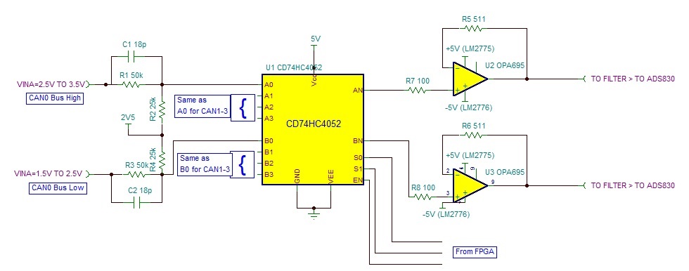
The enclosed schematic (please see below) is part of a CAN Bus tester. The tester is powered from a USB port.
As you can see in the schematic, the can bus signals drives a MUX (CD74HC4052) via a 50K resistor, in parallel with 18pF capacitor, a series 25K resistor and a 2.5V reference voltage (1/3 divider). The user is able to connect the tester to the CAN Bus before connecting it to the USB port, which means, there is no 5V present at VCC pin, while there are signals in the MUX input pins. The current that flows into the MUX is very low (approximately 10mA). The question is, whether the 50K resistor can prevent from the mux going into latch-up or damaging the device? should I add a diode from the power supply to VCC?
Please advise,
Thanks,
Yossy Goldenberg


