This thread has been locked.

If you have a related question, please click the "Ask a related question" button in the top right corner. The newly created question will be automatically linked to this question.

SN74AVC2T245: Please review Schematic and Operation

Other Parts Discussed in Thread: SN74AVC2T245

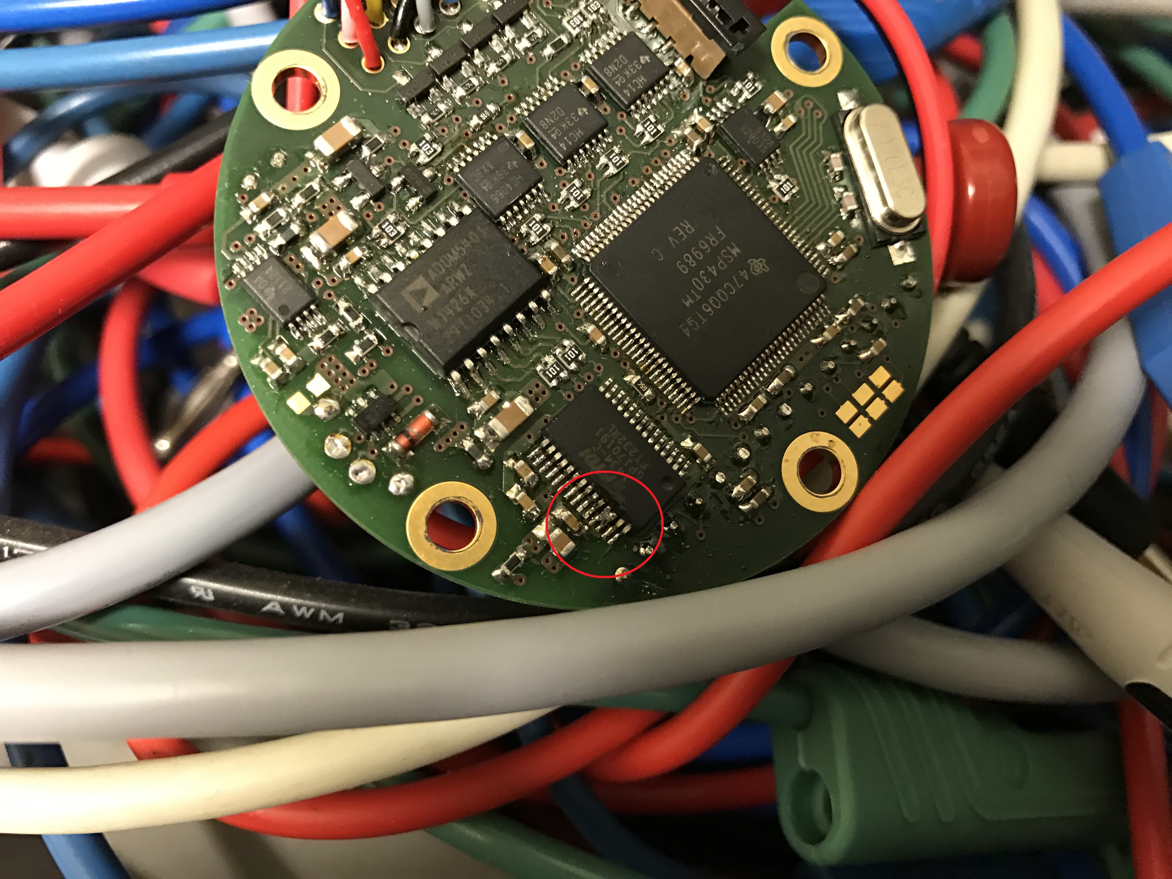
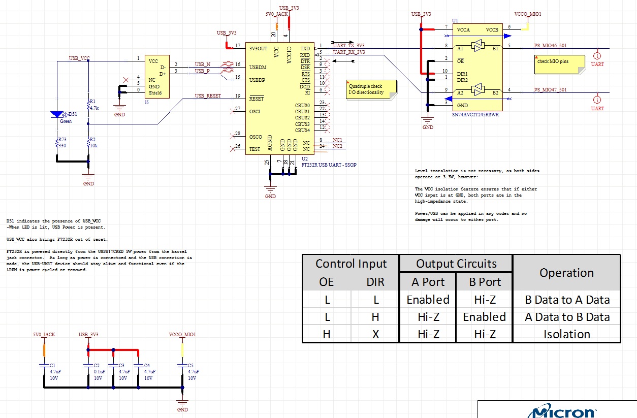
We have a FTDI FT232R UART that is connected to a micro USB port.  The FT232R is connected to a TI SN74AVC2T245 as seen below in the attached schematic diagram.  Both PS_MIO46_501 and PS_MIO47_50 connect to Balls via a Samtec connector on a FPGA daughter board.  The daughter board has been tested and the we are using the same ball connections over USB on another board.  The problem that we have is when the FPGA daughter board is plugged in, the the FTDI chip fails.  

We have done some testing since the FTDI chip would fail simply when connecting the micro USB and external +5V from a wall power supply.  Since, we have removed R1, R2.  We also grounded pin 26 on the FT232R as per FTDI.  The FT232R works as it should until the FPGA daughter board is plugged in and turned on.  Then the fails immediately.  I am just wondering if there is something that was done incorrect on the SN74AVC2T245 that could cause this. 

Datasheets:

www.ti.com/.../sn74avc2t245.pdf

www.ftdichip.com/.../DS_FT232R.pdf

Thanks,

Anthony White

  • You failed to specify what "fails" means.

    Is the FT232R's RXD pin allowed to float?
  • The FT232R fails internally and pins 1,5,9,15,16 are found shorted to ground.

    Before the failure of the FT232R and nothing connected to PS_MIO46_501 and PS_MIO47_501, pins 1,5,9,15,16 measure in the K ohms.

    We can see the FT232R with a host computer, and the FT232R works fine until PS_MIO46_501 and PS_MIO47_501 are connected to our plug in module.

    Pin 5 (RXD) on the FT232R is only connected to pin 9 (A2) of the SN74AVC2T245.


    Thanks,

    Anthony White

  • Hi Anthony!

    One thing I can see immediately when looking at your schematic is the floating TEST pin. This pin has to be tied to GND for normal operation, otherwise the FT232 will sometimes work and sometimes won't. It is a high impedance floating input that changes it's voltage level randomly.

    I had this issue on a prototype myself some time ago:

    Luckily TEST is next to AGND, so a solder connection can be made. I don't know if this fixes your issue or if there is something else, but TEST must be tied to GND, otherwise the FT232 will not work as expected.

    Dennis

  • Yes, we did do that already, but thanks for your response.

    I noted that in my original post that I had found that issue, and grounded pin 26 of the FT232R.


    Thanks,

    Anthony White

  • Anthony White said:
    I noted that in my original post that I had found that issue, and grounded pin 26 of the FT232R.

    Sorry, missed that.

  • Hi Anthony,

    I have moved your post to the translation forum so the engineers that handle the SN74AVC2T245 will see it and respond. Also, I just wanted to mention that I love your schematic -- the added colors make it so much easier to read!
  • Hello Anthony,

    Just based on the schematic, I do not see anything wrong with the way you have connected the AVC2T245. Would it be possible to have OE pulled up while inserting the daughter board and powering it up? Then, pull OE low when you are ready to begin communication. This way at least we can guarantee that the IO ports are disabled until after insertion and power up.