Because of the holidays, TI E2E™ design support forum responses will be delayed from Dec. 25 through Jan. 2. Thank you for your patience.

This thread has been locked.

If you have a related question, please click the "Ask a related question" button in the top right corner. The newly created question will be automatically linked to this question.

TXS0101: Strange output waveform with load

Part Number: TXS0101
Other Parts Discussed in Thread: TXB0101

Hi, I'm using a TXS0101 to translate from 5V to 3.3V (only in one direction).

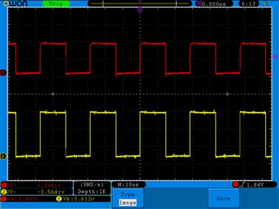
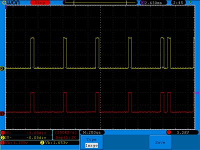
I tested the circuit with no load and obtained the following results:

The bottom signal is the 5V input and the upper is the 3.3V output. Everything seems OK.

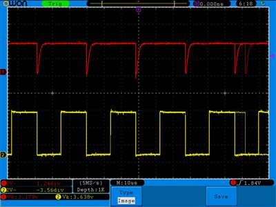
Then, I tested with the board ESP-01 WiFi on pin 7 (RXD on the figure) and obtained the following:

What could be causing this error?

There is nothing connected between the ESP-01 and the TXS0101. 

Thank you for the help.

  • Hi Emiliano,

    I am moving this thread to the translation forum to get the best support.
  • Hello Emiliano,

    I think one of the preliminary measures we could take for debugging this issue is to see if your load (GPIO3 to ESP8266 on the ESP-01) is working as expected. Could you possibly apply a similar signal directly to this load with a function generator or source meter to determine if you are getting what is expected on that end?

    If the load is functioning as expected, then perhaps looking at the board layout could be the next step. Have you included bypass capacitors on the VCCA and VCCB pins?
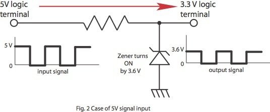
  • The device works fine if I use a Resistor-Zener configuration like this figure (R = 470 Ohm):

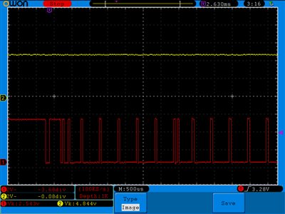
    The input signal without load is this:

    I tested changing the level shifter IC by the TXB0101 and obtain the following. I suppose the signal is correct, but the ESP-01 is still not working.

    In regard to the board layout, I put two capacitors (100uF and 100 nF) on VCCA and one (330 nF) in VCCB. All are Tantalum.

  • Hello Emiliano,

    It looks like there may be some sort of external driver or short that is preventing the line from going low at the output. Can you clarify a few things for us? When you tested it with the TXB, was this on the same board that was used with the failing TXS? When you are probing the I/O of the TXS, are you probing directly at the pins of the translator?
  • It worked using the TXB without adding any external resistor.
    I suppose the internal pullup resistor were affecting the signal.

    Thank to all for your help!