This thread has been locked.

If you have a related question, please click the "Ask a related question" button in the top right corner. The newly created question will be automatically linked to this question.

TMS320F28377D: Hi-Z Trip-Zone state

Part Number: TMS320F28377D
Other Parts Discussed in Thread: 74ACT16244

Hello,

we have following problem with Hi-Z state of a PWM Trip-Zone:

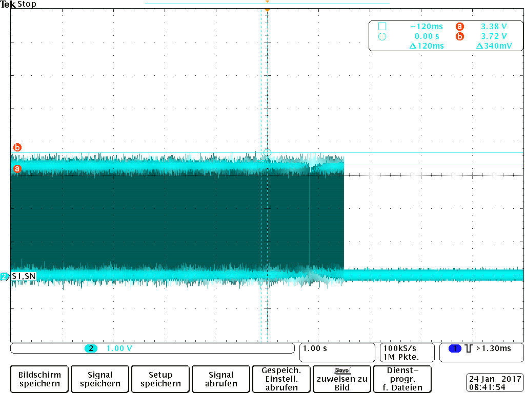
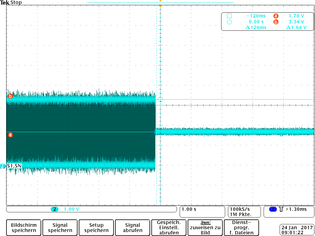
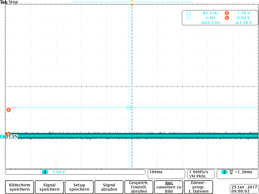
if PWM output signal is low and Trip-Zone event occurs the output pin remains low. If PWM output state is high and Trip-Zone event occurs the output pin goes from high (3.3V) to approximately 1.7V although we have external pull down resistance of 10kOhm at the output and the internal GPIO pull up resistor is off.

Do you have some ideas what the problem can be or is the Hi-Z state with some internal pullup resistor implemented?

Thank you in advance!

Gennadi

  • Hi Gennadi,

    My first thought is this sounds like there may be an issue with your PWM configuration.  Could you post your initialization code for that PWM module which is experiencing the issue?

    Are there any other circuits on this pin which may be driving a voltage on this pin? Is it possible to isolate it from the rest of your system?

    Regards,

    Kris

  • here is our TZ initialization:

    EALLOW;

    // Enable trip zone
    epwmAddr->TZSEL.bit.CBC2 = TZ_ENABLE; 
    epwmAddr->TZSEL.bit.OSHT3 = TZ_ENABLE; 

    // Pulse for clear CBC TZ
    epwmAddr->TZCLR.bit.CBCPULSE = 1; 

    // When trip zone event happen
    epwmAddr->TZCTL.bit.TZA = TZ_HIZ;
    epwmAddr->TZCTL.bit.TZB = TZ_HIZ;

    // Clear trip zone flag
    epwmAddr->TZCLR.bit.OST = 1;
    epwmAddr->TZCLR.bit.CBC = 1;
    epwmAddr->TZCLR.bit.INT = 1;
    EDIS;

    *****************************************************************************

    and here GPIO initialization for PWM's:

    EALLOW;

    GpioCtrlRegs.GPEPUD.all |= 0xFFFE0000; 
    GpioCtrlRegs.GPFPUD.all |= 0x000001FF; 
    GpioDataRegs.GPECLEAR.all |= 0xFFFE0000;
    GpioDataRegs.GPFCLEAR.all |= 0x000001FF; 
    GpioCtrlRegs.GPEDIR.all |= 0xFFFE0000; 
    GpioCtrlRegs.GPFDIR.all |= 0x000001FF; 
    GpioCtrlRegs.GPEMUX2.all &= 0x00000003;
    GpioCtrlRegs.GPFMUX1.all &= 0xFFFC0000; 


    GpioCtrlRegs.GPEMUX2.bit.GPIO145 = 1; // Configure GPIO as EPWM1A
    GpioCtrlRegs.GPEMUX2.bit.GPIO146 = 1; // Configure GPIO as EPWM1B
    GpioCtrlRegs.GPEMUX2.bit.GPIO147 = 1; // Configure GPIO as EPWM2A
    GpioCtrlRegs.GPEMUX2.bit.GPIO148 = 1; // Configure GPIO as EPWM2B
    GpioCtrlRegs.GPEMUX2.bit.GPIO149 = 1; // Configure GPIO as EPWM3A
    GpioCtrlRegs.GPEMUX2.bit.GPIO150 = 1; // Configure GPIO as EPWM3B
    GpioCtrlRegs.GPEMUX2.bit.GPIO151 = 1; // Configure GPIO as EPWM4A
    GpioCtrlRegs.GPEMUX2.bit.GPIO152 = 1; // Configure GPIO as EPWM4B
    GpioCtrlRegs.GPEMUX2.bit.GPIO153 = 1; // Configure GPIO as EPWM5A
    GpioCtrlRegs.GPEMUX2.bit.GPIO154 = 1; // Configure GPIO as EPWM5B
    GpioCtrlRegs.GPEMUX2.bit.GPIO155 = 1; // Configure GPIO as EPWM6A
    GpioCtrlRegs.GPEMUX2.bit.GPIO156 = 1; // Configure GPIO as EPWM6B
    GpioCtrlRegs.GPEMUX2.bit.GPIO157 = 1; // Configure GPIO as EPWM7A
    GpioCtrlRegs.GPEMUX2.bit.GPIO158 = 1; // Configure GPIO as EPWM7B
    GpioCtrlRegs.GPEMUX2.bit.GPIO159 = 1; // Configure GPIO as EPWM8A
    GpioCtrlRegs.GPFMUX1.bit.GPIO160 = 1; // Configure GPIO as EPWM8B
    GpioCtrlRegs.GPFMUX1.bit.GPIO161 = 1; // Configure GPIO as EPWM9A
    GpioCtrlRegs.GPFMUX1.bit.GPIO162 = 1; // Configure GPIO as EPWM9B
    GpioCtrlRegs.GPFMUX1.bit.GPIO163 = 1; // Configure GPIO as EPWM10A
    GpioCtrlRegs.GPFMUX1.bit.GPIO164 = 1; // Configure GPIO as EPWM10B
    GpioCtrlRegs.GPFMUX1.bit.GPIO165 = 1; // Configure GPIO as EPWM11A
    GpioCtrlRegs.GPFMUX1.bit.GPIO166 = 1; // Configure GPIO as EPWM11B
    GpioCtrlRegs.GPFMUX1.bit.GPIO167 = 1; // Configure GPIO as EPWM12A
    GpioCtrlRegs.GPFMUX1.bit.GPIO168 = 1; // Configure GPIO as EPWM12B
    EDIS;

    *****************************************************************************

    And now the hardware circuit on the output:

    see the attached screenshot 1. I did some more tests:

    Test without 240 Ohm  => the signal goes low if TZ event (see screenshot 2)

    Test with 240 Ohm  but without 220pF => the signal goes to 1.7V if TZ event (see screenshot 3)

    Screenshot 1

    Screenshot 2


    Screenshot 3


    I still don't know what a problem is. Is it the 74ACT16244DGG driver input?

  • I would highly suspect the 74ACT16244DGG driver input. It sounds the hi-z is working exactly as we'd expect it to with the external circuit disconnected.  If you disconnect the 240 ohm and check the voltage on the driver input side, I'm guessing you will see a voltage greater than or equal to 1.7 V.  Can you check that?

    Regards,

    Kris

  • Hi Kris,

    yes, you are right. If I disconnect the 240 ohm I see 1,76V on the input of 74ACT16244DGG, but just if the input was high before disconnecting. Do you have some idea why? What is the input circuit of 74ACT16244DGG (I can't find it in datasheet).

    If we have 1 kohm pull-down on the input it seems to work properly, but 1 kohm is to small for our application and is large load for DSP output.

  • Hi Gennadi,

    Can you check to make sure the pull up resistor on the C2000 device is disabled? This is done via the GPxPUD disable register where 'x' is the GPIO port of the pin.

    Also, can you describe the process you are going through to remove the 240 ohm resistor? Is the driver input physically disconnected from the pull down resistor on the C2000 side, and therefore the input is floating?

    Thanks,
    Kris
  • Hi Kris,

    1) yes, the pull up on the C2000 is off

    2) yes, I disconnected one input of 74ACT16244DGG, so there is no physical connection to the 10k pull down 

    3) if I connect it physicaly to 3.3V and then disconnect it again -> I can meas 1.76V on the input (screenshot 1)

    4) If I don't connect it to some voltage potential -> I can meas 0V on the input (screenshot 2)

    screenshot 1


    screenshot 2


    Regards,

    Gennadi

  • Hi Gennadi,

    In an effort to get you a resolution faster I have requested this post be moved over to the analog forum. They should be able to help you with this debug quite a bit faster, since it seems we have ruled the C2000 device out as the issue. Please let us know if there is any other assistance we can provide.

    Regards,
    Kris
  • Thanks Kris and hi Gennadi,

    To get us started on troubleshooting the buffer, can you post the schematic section surrounding the 74ACT16244?
  • Hi Emrys,

    her are the schematics screenshots surrounding the buffer

    Regards,

    Gennadi

  • Thank you Gennadi,

    I don't see the power pins for the 74ACT16244, however I assume it is being powered from a 5V rail and has appropriate bypass capacitors.

    Is it possible to get a measurement of the supply current (Icc) and a scope shot of the output of this device when the 1.76V input occurs vs when it does not? It is possible that the input voltage slowly passing the device's switching threshold could cause internal oscillation or a linear response.

    I noticed that the RC circuit on the input is filtering very high frequency content - is it possible to remove this filter from the circuit? If not, I believe it would be possible to achieve a very similar roll-off frequency by removing the 220pF capacitor and increase the series resistance from 240 ohm to 10kohm - utilizing the small input capacitance of the CMOS inputs as part of the low-pass filter (Ci = 4.5 pF typical).
  • Hi Emrys,

    unfortunately we can not meas the Icc current. We have the same issue if we remove the filter circuit from the input and just have 10kohm pull down resistance directly at the input. The buffer works properly just with smaller pull down resistance (1kOhm). I have passed the problem to my hardware colleagues. Do you have some Idea for recommended pull down resistance at the input?

    Thank you

    Gennadi

  • Hi Gennadi,

    Since those are CMOS inputs, a 10k pull-down should be more than sufficient. I want to get some of those parts into my lab to do some tests. It will take some time though since they aren't standard devices we have in local stock.
  • Hi Emrys,

    Thank you. I hope you can reproduce it in your lab.

  • Gennadi,

    I wasn't able to reproduce this issue in the lab. We were able to get an input to hang at 1.7V very briefly when there was no pull-down on that input, but with a 10kohm resistor it always went back to zero quickly after charged to 3.3V.

    Have you tried swapping out the chip to see if its a failure from an EOS or ESD event?