This thread has been locked.

If you have a related question, please click the "Ask a related question" button in the top right corner. The newly created question will be automatically linked to this question.

SN74LVC1G123: Issues with Q signal staying high longer than expected

Part Number: SN74LVC1G123

Hello,

I am having issues with the multivabrator being stuck high for very long periods of time. It will trigger as expected when the function generator's output is set to on, but after the function generator is turned off the circuit remains high. Sometimes it will come down after a minute or so, but other times it will not switch back to low. I have attached a schematic of how the circuit is currently configured. I have tried switching the resistor and capacitor on Rext and C ext, but the same thing happens. I also added the load capacitor and resistor, but still the same results. Please let me know if you need any other information.

Thank you,


Al "Joe" Luck

  • Hello,

    I am not sure if it is a mistake in your drawing or if you have it connected this way, but it seems you have pin5 connected to the 5V and pin8 connected to be the output. The device has pins 5 through 8 in a different order from the way you have it connected in your drawing.

    Is it possible that you have your device connected incorrectly? 

    Please see diagram below for reference

    If not, would you be willing to share your input pulse and output on the oscilloscope.

    Best,
    Michael

  • Michael,

    Thank you for the response. Yes I miss labeled the schematic I sent to you. The left side is properly connected the same as the picture from the datasheet above.

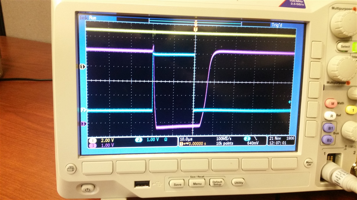
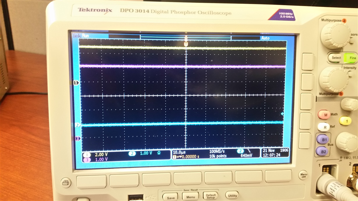
    I have attached a scope plots of both with the input on and the input off. The output of the multivabrator is on channel one. The output of the function generator is on channel two, while channel 3 is the input to the multivabrator after the mosfet. Please let me know if you need any other explanation.

    Thanks,

    Joe

  • Hello Al,

    The device will trigger based on the voltage seen at pin 7. If the output is staying high, this would seem to suggest that PIN7 is staying low/below the internal threshold for switching.

    Is Pin7 showing a low voltage at all times? The timing diagram in Figure 2 is a good reference for what Pin7 should look like to trigger the output.
    Please let me know what you see or if you find out any additional information.

    Best,
    Michael
  • Michael,

    Thank you for your assistance. After checking the pin 7 I saw that it's state was never changing. This lead me to replacing the multivibrator again and it worked this time. I am not sure what happened with the first two, but I am happy to see it work.

    Thank you,

    Joe 

  • Hey Joe,

    Very happy to help, glad you were able to figure it out.
    Please continue to use these forums when you have questions as we are always happy to help.

    Best,
    Michael