This thread has been locked.

If you have a related question, please click the "Ask a related question" button in the top right corner. The newly created question will be automatically linked to this question.

LSF0108: The output signal distortion

Part Number: LSF0108

Dear TI:

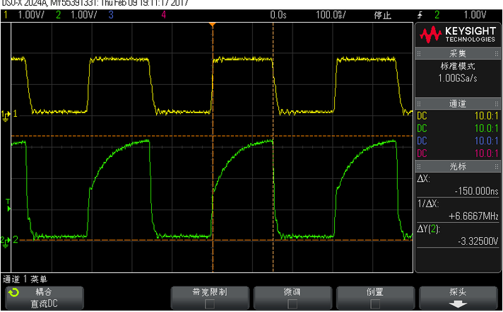
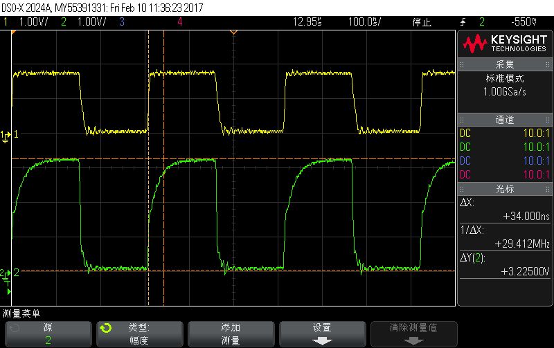
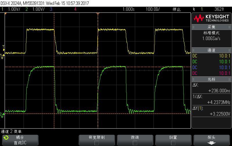
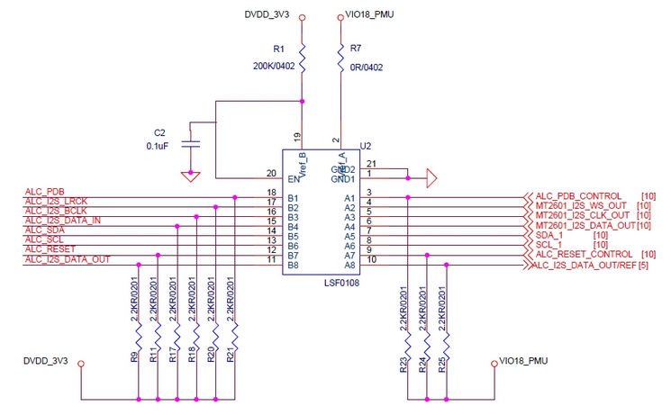
Use LSF0108 to IIS level conversion , The output signal distortion. Vin = 1.8V(yellow) , Vout = 3.3V(green). 

Now pull up resistors with 2.2 K. Increases to 4.7 K distortion is more serious . Reduce to 300Ω when the output without distortion , but output  cannot be pull down 0 level. Please see the following screenshots. 

Many Thanks.

  • Hi,

    The issues you are running into come from a typical trade off between speed and current capability of external devices when using the LSF family for voltage translation. A lower resistance will give you the faster rise time as you see with the second scope capture you submitted, but as the image below shows, you are sinking current into the low side device when the lines are low. Sinking too much current into the low side device could exceed the current capabilities, or the Vol spec, of that device, could you explain what you are using there?

    Based on the information provided in your scope capture, could you try using a 700Ω resistor on the high side (3.3v) and a 4.7kΩ resistor on the low side (1.8V)? This should cut your charge time to about 1/3 on the high side while still limiting the current your external device is sinking.

    For additional information in designing with this device, please refer to this app note Voltage-Level Translation With the LSF Family

    Regards,

    Aaron Goodson

  • Hi Aaron:

    I use the input chip internal configuration of pull-up resistor(dozens of KΩ) in the input side(1.8V) and a 1KΩ resistor in the ouput side(3.3V). Please look at the following pictures. I try using 1KΩ and 2.2KΩ and 4.7KΩ pull-up resistor in the input , but almost make no difference ouput.

    In view of this kind of situation, Do you have any good suggestions? Thanks you very much.

  • Hardy,

    Could you try decreasing the resistance on the 3.3V side even further? The 1kohm resistor on the 3.3V input seems to have gotten the waveform on channel 2 closer to what you are expecting. Have you tried the 700 ohm resistor I suggested originally? 

    Regards,

    Aaron Goodson

  • Dear Aaron:

    I tried to use a 680Ω resistor on the high side (3.3v) and a 4.7kΩ resistor on the low side (1.8V).  Please look at the following pictures. There is a good change along the rising edge, but output  cannot be pull down 0 level.

  • Hardy,

    This waveform is very good for the LSF family. With this being a passive family of devices, there will always be a slight voltage gain across it which will cause your signal to float slightly. Your signal is floating less than 100mV above ground from what I am seeing on your scope capture. You could check the Vol spec for your device on the low side to verify that it is higher than the floating voltage that you are seeing on your capture, but most logic devices have a Vol of ~0.5V so this should not be an issue. 

    Regards,

    Aaron