


Other Parts Discussed in Thread: CD40106B
I have made the mistake of doing what Ethan proposed in his e2e post: <https://e2e.ti.com/support/logic/f/151/t/536693>
Which is to filter an input signal line of an CMOS OR gate using an RC filter. After reading SCBA004 <www.ti.com/.../scba004d.pdf> I am now understanding why this is a bad idea.
But, I am having a hard time solving the problem for my application. My condensed circuit is shown here:
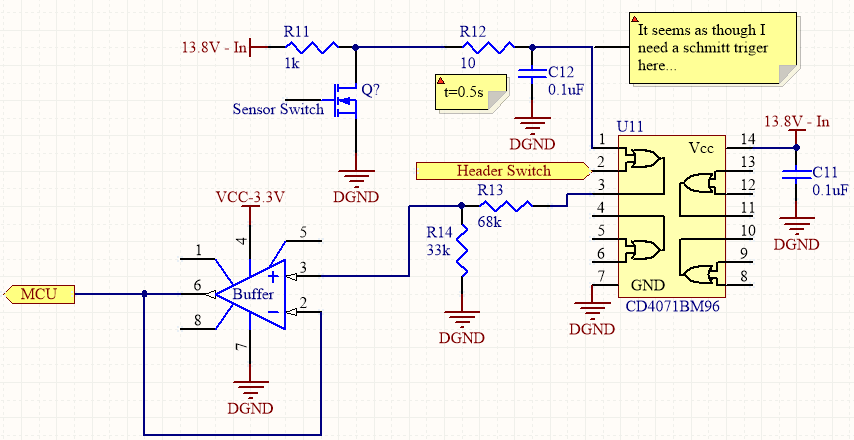
It seems that I should be able to insert a schmitt trigger between the RC filter and pin 1 of CD4071B, but being that I have never used a schmitt trigger before I was hoping to confirm with an expert if this is a good idea or not. If this is a good solution, how should I pick my schmitt trigger? I am unable to find one online that can support my voltage requirements. The best I have found (I think) is one by TI that can support up to 5.5V or so (SN74LVC1G17DBVR). but this means that I would have to add a voltage divider to bring the voltage down, which I don't want to have to do because I am trying to keep my parts count at a minimum (if possible).
There must be a simple solution to this that I am not considering, as I am sure that it is often done in industrial applications.
Also, I know what your probably thinking. Why not just spare an extra processor pin and OR them in software? I can't do this because part of this circuit is embedded into a cable exterior of the electronic control box and I am limited on how many wires I can use.
Thank you!
Marshall

