This thread has been locked.

If you have a related question, please click the "Ask a related question" button in the top right corner. The newly created question will be automatically linked to this question.

CD74HCT132: My chips are not working, please help me.

Part Number: CD74HCT132

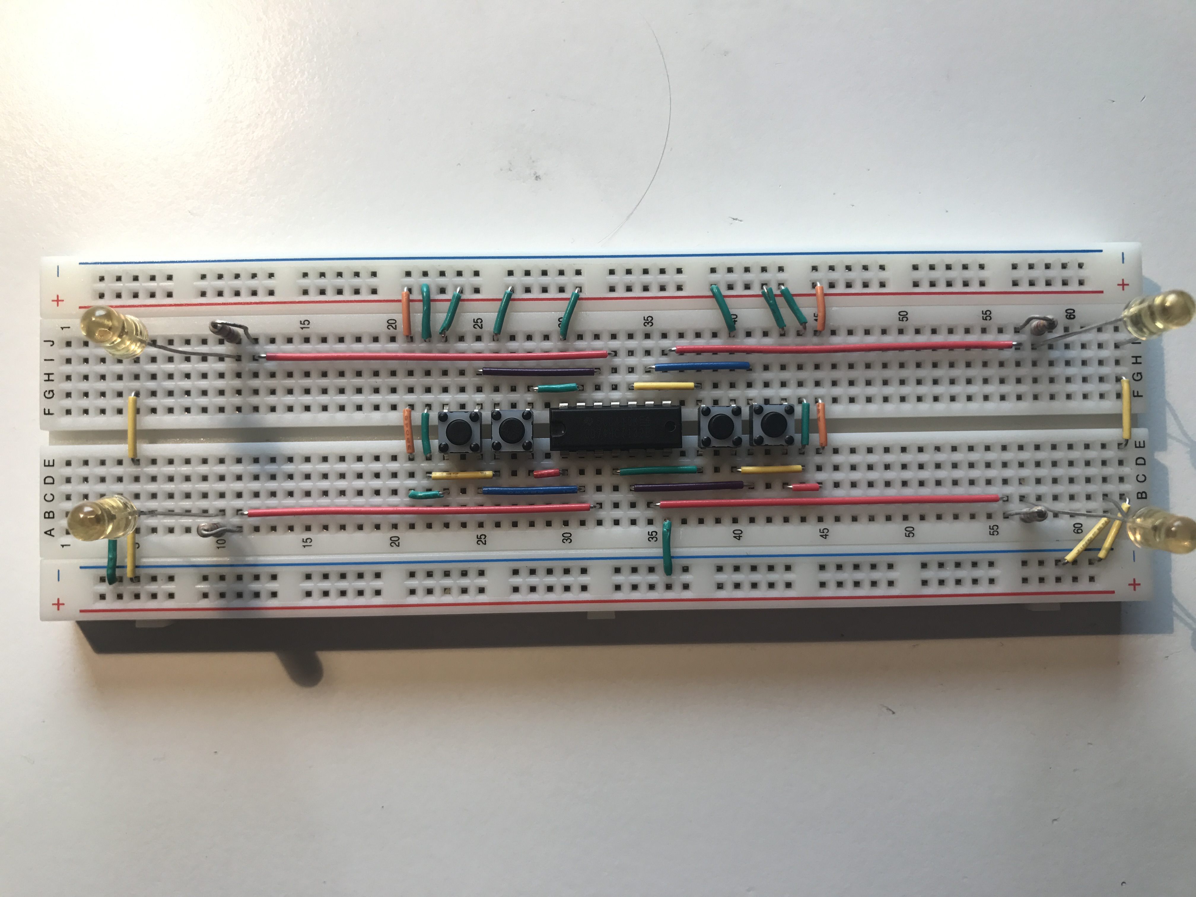
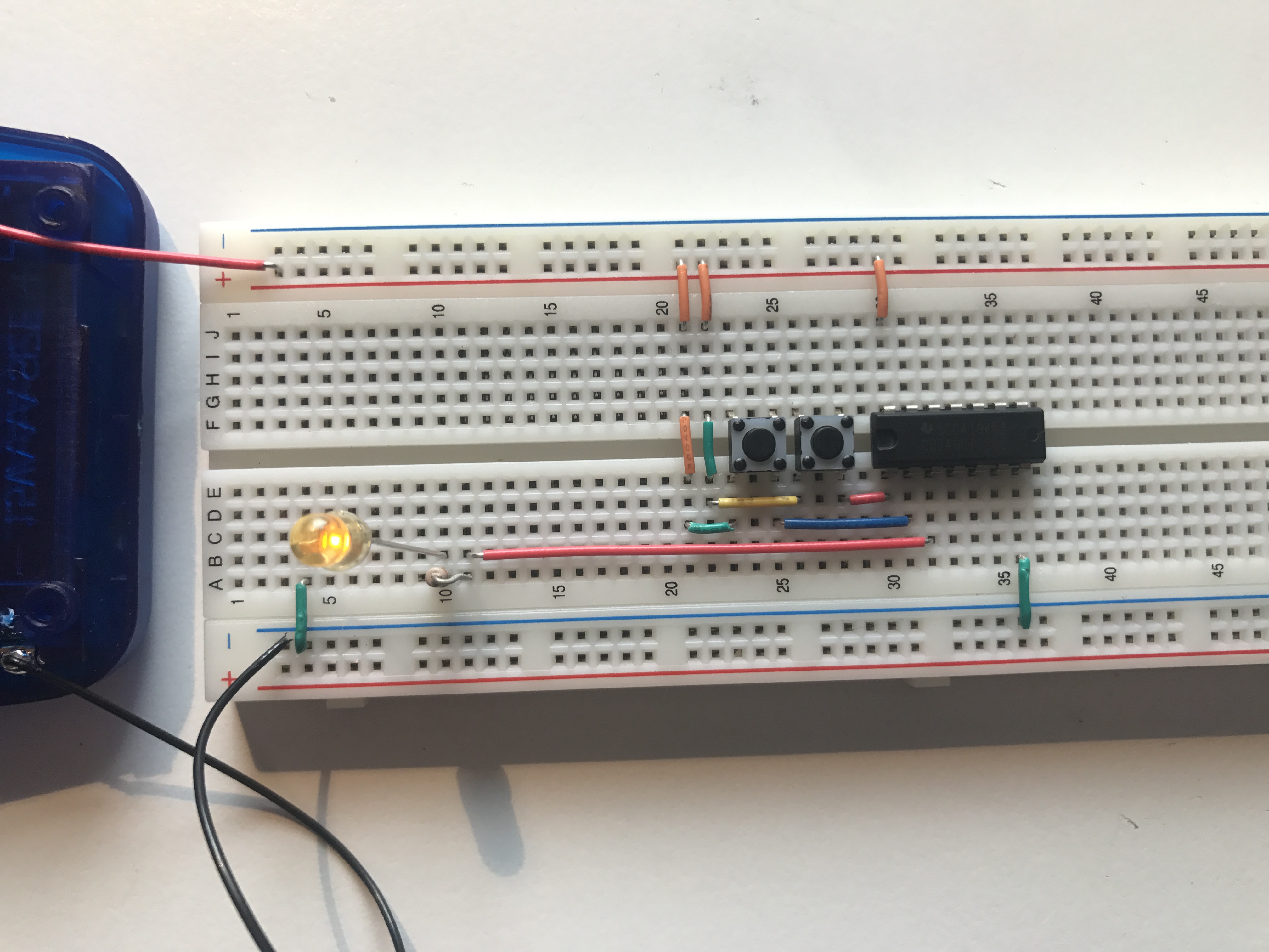
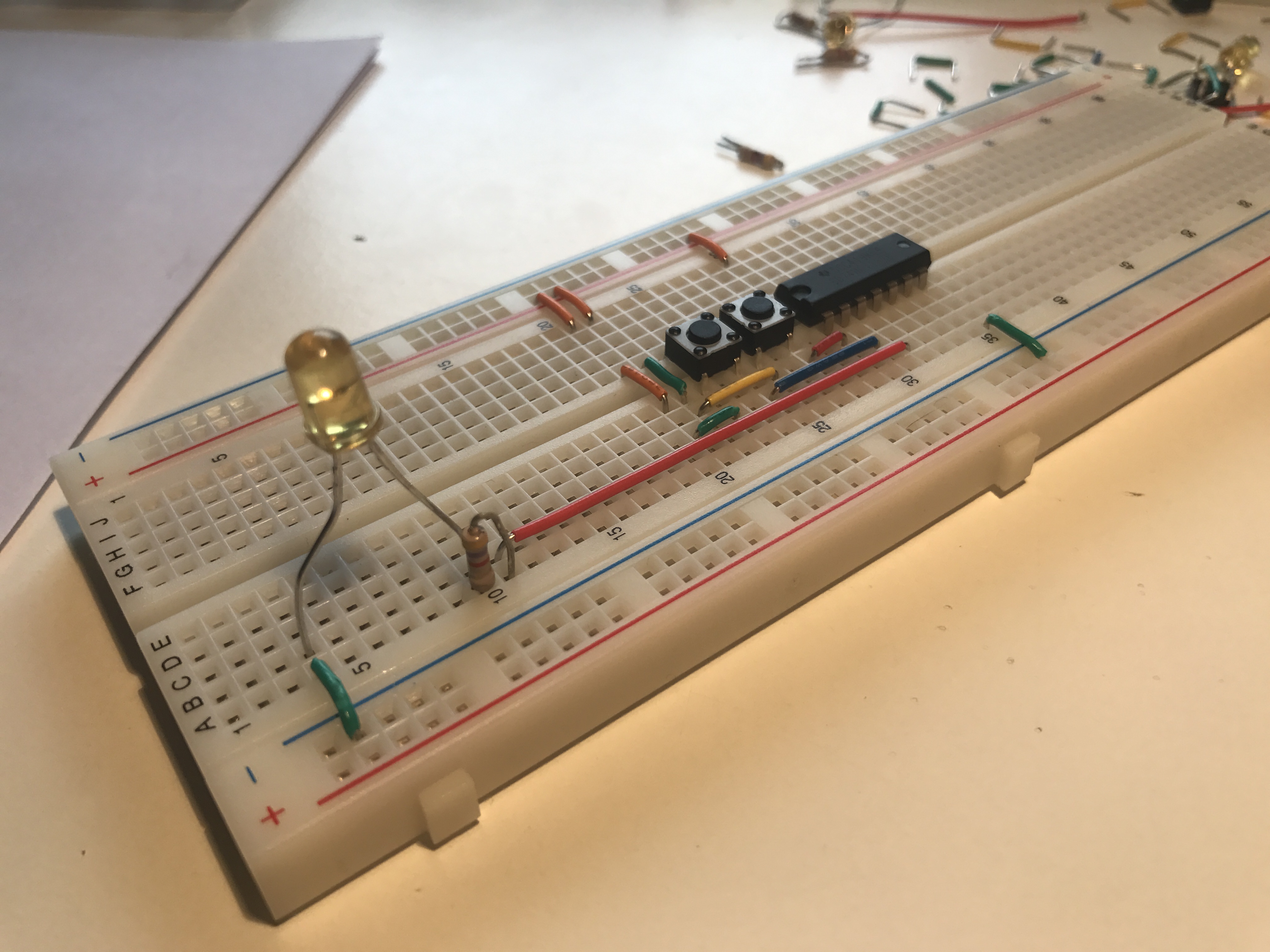
hi, ran into some trouble with  the TI chip that is mentioned above. it's a quad nAnd gate chip. I am using a 4,5 V input and I connected pin 14 to VCC and pin 7 to GDD. It seems that every chip I use just burns through or something and then it lets all signals through. (I connected imput 1A and 1B with switches to VCC). The light at output 1Y burns, Even if there is no signal at all coming through 1A and 1B. What did I do wrong?

  • Hello,

    Can you share a schematic of what you have done? Is the 'light at output 1Y' an LED? Please show your circuit so we can help troubleshoot. A picture, drawing, or full description would be helpful.

  • The light at Y1 is indeed a LED. The buttons, my power source, the resistor, wires and LEDs are all working for sure. In the first picture I connected every gate. Nothing happens when I connect power to the power rails it does not matter which buttons I press. But when I connect ground to one of the inputs for a second, the light turns on. Then it turns of after about 10 seconds, but it also turns of when I press one of the buttons. It only turns back on again when I hit one of the imputs with Ground again. Its a nand gate so I expected the light to stay on untill one of the buttons was pressed (or both).

  • don't read the last sentence. I meant I expect the light to turn off when both buttons are pressed at the same time.
  • That's a fantastic layout - very nicely done and easy to follow.

    The problem you have is that the inputs are only being driven high - there is nothing here to drive them low again.

    When one of your switches is open, the associated input is floating, which is generally a bad thing for CMOS devices. You need to add pull-down resistors to each input to ensure that they return to 0V when not being forced to VCC. I would recommend 10kΩ resistors from each input pin of the device to ground.

  • Omg Thank you so so so much!! It works now!! I have been playing around with circuits for only a few days now so I had No idea! You are Awesome! I was afraid I could throw all the chips away. Thnx again!!