This thread has been locked.

If you have a related question, please click the "Ask a related question" button in the top right corner. The newly created question will be automatically linked to this question.

TXS0102: Level converter works only on one direction

Part Number: TXS0102
Other Parts Discussed in Thread: TXB0102

Hi all

I'm using a TXS0102 to interface a 1.8v device radio module with a 3.3v mcu.

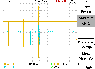
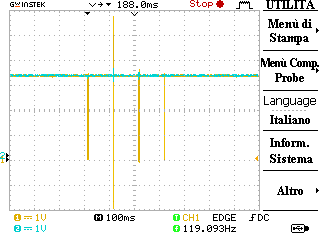
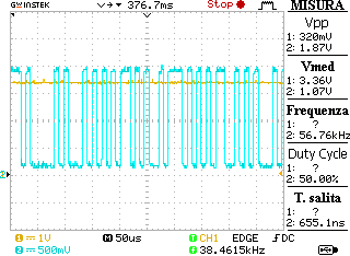
As the data were not recived form the mcu, I probed the lines and I noticed that the AT command is successfully sent to the TXS0102 from the 3.3v device, the AT command is successfully translated to 1.8v and sent to the radio module, the radio module responds to the command correctly at 1.8v and the 1.8v signal is NOT translated to 3.3v, so the mcu do not recive the data.

what could cause such a behaviour?

Regards,

Andrea.

  • Hi Andrea,
    Can you provide scope shots of the 1.8V to 3.3V translation?

    It would also be helpful to know the following:
    maximum data rate
    1.8V driver strength ( max sink current )
    edge rate of 1.8V driver
    load capacitance (on both sides of the TXS device) - if line capacitance is unknowns, the number of devices connected and trace lengths will be helpful.
  • Hello,

    the data line is a 115200 baud uart.

    the 1.8v is the aux voltage from the radio module. the declared maximum output current is of 100mA

    there are 100nF capacitors on reference voltages (both 1.8v and 3.3v)

    on the data line, there are 56pF capacitor to filter rf noise (self resonant at ~1Ghz)

    data traces lengths are less than 1 cm for the 1.8v line around 3 cm  for the 3.3v line.

    Here is the oscilloscope with CH1 (yellow) the 3.3v line that goes from the mcu to the radio module and CH2 (blue) the 1.8v from the radio module to the mcu

    in the next shot i moved the probe from the 1.8v side of the line that goes from the module to the mcu to the 3.3v side.

    Also, here is a closer look of the 1.8v signal from the radio module to the mcu

    Let me know if you have any solution

    Thank you,

    Andrea.

  • Thanks for the info/scope shots.

    It's likely that the added capacitance on the I/O lines is causing issues with the translation process. I have asked our translation expert to take a closer look at this post. While we wait on his response, can you grab a zoomed in scope shot of the translation? It's hard to tell what's happening on the edges from the above images. I'm looking for where the one-shot triggers, which should be within the first 30-100 ns after a rising edge (the scale up there is 50us; 500ns scale would probably show what we need to see)
  • Hey Andrea,

    Is 1.8 tied to Vcca and is 3.3 tied to Vccb? How long are you waiting before you send data in the opposite direction? If you want to test the capacitance theory you can remove that 56 puff cap and then rerun your signals.

    Nick
  • Hi Nick

    Yes, Vcca is tied to 1.8v capacitor and vccb is tied to 3.3v, Both with 100nF bypass cap.

    Since the radio module has a quite long boot time, I wait some seconds before the first command is sent to the device.

    I will try to remove the capacitor and letyou know asap.

    Thanks for your help,
    Andrea.
  • Hi,

    I tried to remove the capacitors but it did not work.

    Also, i noticed that the radio module datasheet reports a "low" logic level voltage of 0 to 450mV, which is higer than the 0.15V stated in the TXS0102 datasheet.

    I noticed that the TXB0102 converter has the same exact footprint of the TXS0102, it has a low level treshold of 0.35*Vcca = 0.63V @1.8V Vcca and a rise/fall rate of 30ns/V instead of 10ns/V. 

    Do you think that replacing the TXS0102 with a TXB0102 could help solving the problem?

    Regards,

    Andrea.

  • Nice pickup on the low voltage value of the radio module. It is definitely worth a shot since the scope capture you have is around 200mV or so I'd guess. One thing to look out for is the line/load capacitance you are trying to drive. The TXB is only designed to run with <70pF on it. The TXS is able to handle more than that and is better for higher capacitance driving. Also, one side benefit of the switch is that the TXB actually consumes ~510uA fewer than the TXS with the same reference voltage potentials you have in your setup.

    As an aside is it possible to get the part number of the radio module and a little info on your end application to help in trouble shooting and part selection? If proprietary, don't worry about it.

    Nick
  • Hi Nick,

    The current capacitance on the line is 68pF, but I tinhk we can decrease it, since the important feature of the capacitors for us is the self resonant frequency (we will have a GSM/UMTS/LTE antenna very close to the device)

    The radio module is a Telit LE910.

    Let me know what you think, if we need to find a lower value capacitor (and how much we should decrease the capacitance) or 68pF looks good for you.

    Regards,

    Andrea.

  • I'd say try and switch the devices, TXS to TXB, and see if you can get the capacitance to around 25 or 30% margin; i.e. 53pF or 49pF. It should be fine if you make the change with the 68pF on the line since it does look like the Vil value and the high margin that the radio module supplies is the issue, but if we get it that low than I think it's pretty safe to consider capacitance as not being your problem. Always ruling stuff out is nice! Plus I think the chip change will have a good chance of resolving the issue.

    Nick

    If this answered your question, please hit the green "Verify Answer" button below. If not, let us know your other questions and we'll be happy to help.